Digital I/O: reading buttons, driving LEDs
GPIO — General-Purpose Input/Output — is how a microcontroller talks to the world. Each GPIO pin can be configured (in software) as an input (to read a signal) or an output (to drive a signal). This is the core of using a microcontroller: reading buttons and sensors, driving LEDs and loads.
Digital output: driving a signal
Configure a GPIO pin as a digital output and your code can set it HIGH or LOW:
- Set HIGH: the pin outputs the supply voltage (~3.3V on a 3.3V chip, ~5V on a 5V chip).
- Set LOW: the pin outputs ~0V (ground).
This is how the microcontroller controls things. The classic first project — blinking an LED — sets a pin HIGH (LED on), waits, sets it LOW (LED off), repeats.
A digital output can directly drive a small load:
- An LED (with its current-limit resistor from L1) — the pin sources the LED's ~20mA directly. Set HIGH = LED on.
- A logic input of another chip — the HIGH/LOW signals another device.
- The control input of a transistor (L2) — to switch a larger load (next slide).
The code controls the pin; the pin controls the world (directly for small things, via a transistor for big things).
Digital input: reading a signal
Configure a GPIO pin as a digital input and your code can read whether it's HIGH or LOW:
- Reads HIGH if the voltage applied to the pin is near the supply.
- Reads LOW if the voltage is near ground.
This is how the microcontroller senses things:
- A button: wired so pressing it changes the pin's voltage. Your code reads the pin to detect the press.
- A switch: open/closed changes the pin state.
- A digital sensor output: a sensor that signals HIGH/LOW (a motion detector's "motion/no-motion" output, a limit switch).
The floating-input rule (L1/L3) — critical for inputs
Here's where L1 and L3 come back: a digital input must have a defined level. If the input is connected to nothing when it should read (e.g., a button that's not pressed leaves the pin floating), it picks up noise and reads randomly (the floating-input problem from L3).
The fix (from L1): a pull-up or pull-down resistor:
- Pull-up: holds the input HIGH by default; a button to ground pulls it LOW when pressed. (Unpressed = HIGH, pressed = LOW.)
- Pull-down: holds the input LOW by default; a button to the supply pulls it HIGH when pressed.
Many microcontrollers have internal pull-up resistors you enable in software (e.g., INPUT_PULLUP in Arduino) — saving an external resistor. But you must enable it. The most common beginner microcontroller bug is a button that "reads randomly" because the input is floating — no external pull resistor AND no internal pull-up enabled.
The rule: every digital input needs a defined level — an external pull resistor or the internal one enabled. Never leave an input floating.
Button wiring example
A typical button on a microcontroller input:
- Button connects the GPIO pin to ground.
- The pin has a pull-up (external resistor to the supply, or the internal pull-up enabled in code).
- Unpressed: the pull-up holds the pin HIGH → code reads HIGH.
- Pressed: the button connects the pin to ground → pin goes LOW → code reads LOW.
So in code, a LOW reading means "pressed" (with a pull-up configuration). It feels backwards at first (pressed = LOW), but it's the standard, reliable wiring. (Pull-down wiring inverts it: pressed = HIGH.)
Reading + driving — the basic interaction
Most microcontroller projects are loops of:
- Read inputs (buttons, sensors) — what's happening in the world?
- Decide (your code's logic) — what should happen?
- Drive outputs (LEDs, loads) — make it happen.
A thermostat: read the temperature sensor (input), compare to the setpoint (decide), drive the heater relay (output). A light controller: read the button (input), toggle the state (decide), drive the LED (output). This sense-decide-act loop, using GPIO for the sensing and acting, is the essence of embedded control.
Pin numbering + configuration
In code, you refer to pins by number (or name), configure each as input or output, and then read or write them:
- Configure: "pin 13 is an output", "pin 2 is an input with pull-up."
- Drive: "set pin 13 HIGH."
- Read: "what's the state of pin 2?"
The exact syntax depends on the platform (Arduino's pinMode, digitalWrite, digitalRead), but the concepts are universal: configure the pin's direction, then drive (output) or read (input) it.
What's coming
This slide covered digital I/O — the on/off world. But GPIO does more:
- The current limit — a pin can only drive ~20mA, so big loads need a transistor (the L2 tie-in, next slide).
- Analog input (ADC) — reading continuously-varying voltages, not just HIGH/LOW (slide 2.3).
- PWM output — approximating analog output for dimming and speed control (slide 2.3).
The next slide covers the crucial current-limit constraint and the microcontroller-drives-a-load pattern that connects L4 back to L2.
A microcontroller pin set as a digital OUTPUT and driven HIGH (on a 3.3V chip) provides:
The GPIO current limit + driving real loads (L2 tie-in)
A GPIO pin can drive only a small current — typically about 20mA. That's enough for an LED, but nowhere near enough for a motor, relay, or any real load. This constraint, and the transistor pattern that overcomes it, is the direct bridge from L4 back to L2.
The current limit
Each GPIO pin has a maximum current it can source (supply) or sink (absorb) — typically around 20mA (check your specific chip's datasheet; some pins or chips allow more or less). Exceed it and you damage the pin, potentially the whole microcontroller.
What 20mA can drive:
- An LED (with its current-limit resistor) — LEDs run at ~20mA, right at the limit. ✓
- A logic input of another chip (draws almost nothing). ✓
- The control input (base/gate) of a transistor (draws little). ✓
What 20mA CANNOT drive:
- A motor (hundreds of mA to amps). ✗
- A relay coil (tens to hundreds of mA). ✗
- A solenoid, a pump, a heater (hundreds of mA to amps). ✗
- A string of LEDs (adds up past 20mA). ✗
Connect any of these directly to a GPIO pin and you exceed the limit — the pin (and microcontroller) is damaged. This is one of the most common, and most destructive, beginner mistakes.
The solution: the transistor (L2)
The fix is exactly the microcontroller-drives-a-load pattern from L2:
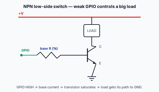
- The GPIO pin provides only the small control signal (well within its 20mA limit).
- A base/gate resistor connects the pin to a transistor or MOSFET (L2).
- The transistor switches the load, drawing the load's larger current from a separate supply capable of providing it — NOT through the microcontroller.
- A flyback diode across the load if it's inductive (motor, relay, solenoid) — to clamp the switch-off spike (L2).
- Common ground between the microcontroller and the load supply.
The microcontroller controls; the transistor carries the power; the separate supply provides the current. The GPIO pin only ever supplies the tiny base/gate current.
Worked example: ESP32 driving a 12V motor
You want an ESP32 (3.3V GPIO, ~20mA limit) to switch a 12V, 500mA motor:
- A logic-level N-channel MOSFET (turns on fully at 3.3V gate).
- Motor from +12V to MOSFET drain; MOSFET source to ground.
- Gate through a ~100Ω resistor to the ESP32 GPIO; a 10k pull-down from gate to ground.
- A flyback diode across the motor (cathode to +12V) — the motor is inductive.
- The ESP32 ground and the 12V supply ground connected (common ground).
Now: ESP32 GPIO HIGH → MOSFET on → motor runs (500mA from the 12V supply). GPIO LOW → MOSFET off → motor stops, flyback diode absorbing the kick. The ESP32 pin supplied only the tiny gate current — nowhere near its 20mA limit. The 500mA came entirely from the 12V supply.
Why this is the most important L4 ↔ L2 connection
This pattern is where the microcontroller (L4) meets the components (L2). A microcontroller is useless for control if it can't drive real loads — and it can't drive them directly. The transistor is the muscle the microcontroller's brain commands.
Almost every project where a microcontroller does something physical — turning on a pump, running a motor, switching a light, driving a heater — uses this pattern. Master it and you can make a microcontroller control anything; ignore it and you fry pins.
Driver chips: the pattern, packaged
For convenience, the transistor-switching pattern is often packaged into driver chips and modules:
- Relay modules — a relay + its driving transistor + flyback diode on a small board. Feed it a GPIO signal; it switches the relay (and whatever the relay controls, including AC mains with isolation).
- Motor driver ICs / modules (e.g., L298N, DRV8833, or MOSFET-based boards) — multiple transistor switches packaged to drive motors, including reversing direction.
- MOSFET breakout boards — a logic-level MOSFET + gate resistor + pull-down, ready to switch a load from a GPIO.
These modules ARE the transistor pattern, pre-built and convenient. Underneath, they're doing exactly what you'd build from a bare transistor — the GPIO drives a transistor that switches the load. Using a module doesn't change the principle; it just saves you wiring it from discrete parts. These driver modules are widely available alongside the bare components.
The non-negotiable rules
When a microcontroller drives a real load:
- Never connect a load drawing more than the pin's limit (~20mA) directly to a GPIO. Use a transistor.
- For inductive loads (motor, relay, solenoid), always include a flyback diode (L2).
- Use a separate supply for the load, sized for its current, with a common ground.
- For a MOSFET driven from logic, use a logic-level MOSFET (L2) — fully on at 3.3V/5V.
Break rule 1 and you fry the microcontroller. Break rule 2 and you fry the transistor. These rules are the accumulated wisdom of L2, applied every time a microcontroller controls a real load.
The next slide covers the other GPIO capabilities beyond simple digital I/O: analog input (the ADC, reading varying voltages) and PWM output (approximating analog control).
To switch a 1A motor from a GPIO pin (limited to ~20mA), you:
Analog input (ADC) + PWM output
Beyond digital HIGH/LOW, microcontrollers offer two more GPIO capabilities that bridge the analog and digital worlds (L3): analog input (the ADC, reading continuously-varying voltages) and PWM output (approximating analog control with digital switching).
Analog input: the ADC (L3)
A digital input only sees HIGH or LOW — but many sensors output a continuously-varying voltage. To read those, you use a pin's analog input capability, backed by the microcontroller's ADC (Analog-to-Digital Converter, from L3).
The ADC converts the pin's voltage into a number:
- A 12-bit ADC (like the ESP32's) gives values 0–4095.
- A 10-bit ADC (like the Arduino Uno's) gives values 0–1023.
- 0 represents 0V; the maximum value represents the reference voltage (often the supply, ~3.3V).
So reading a sensor at 1.65V on a 12-bit, 3.3V ADC gives roughly 2048 (halfway). Your code reads this number and interprets it (e.g., converting it back to a temperature, a moisture level, a position).
What you read with analog input:
- Potentiometers — the wiper voltage (a voltage divider, L1) varies with position. Read it to get the knob's position.
- Analog sensors — temperature (some sensors output a proportional voltage), light (a light-dependent voltage), the capacitive moisture sensor's analog output, etc.
- A battery's voltage — through a voltage divider (L1) to bring it into the ADC's range, then read to monitor charge level.
The ADC is where L1 (voltage dividers), L3 (analog-to-digital), and L4 (the microcontroller) converge. A huge fraction of projects are: analog sensor → (divider if needed) → ADC → microcontroller processes the number.
Analog input gotchas
- Stay within the ADC's range. The input voltage must not exceed the reference (usually the supply). A higher voltage needs a divider (L1) to scale it down — and exceeding the pin's absolute max can damage it.
- Not every pin has ADC. Only specific pins connect to the ADC. Check the pinout (L0's datasheet skill) for which pins are analog-capable.
- The ESP32's ADC quirks. The ESP32's ADC has some non-linearity and the ADC2 channels conflict with Wi-Fi — practical details you'll meet, documented in its datasheet.
PWM output: analog-like control (L3)
Microcontrollers often can't output a true analog voltage (no DAC, or a limited one) — but they achieve analog-like control with PWM (Pulse-Width Modulation), from L3.
PWM rapidly switches a pin HIGH and LOW, varying the duty cycle (the proportion of time it's HIGH):
- 100% duty cycle → always HIGH → full effective output.
- 50% duty cycle → HIGH half the time → effective half-output.
- 25% duty cycle → effective quarter-output.
Averaged out (by the inertia of the load, or an RC filter from L1), this produces a controllable effective level using only digital switching.
What you control with PWM:
- LED brightness — vary the duty cycle to dim an LED (50% looks roughly half-bright). This is how dimmable LED indicators work.
- Motor speed — PWM the transistor driving a motor (L2); higher duty cycle = faster. (The motor's inertia averages the pulses.)
- Servo position — servos read a specific PWM signal to set their angle.
- A rough analog voltage — PWM + an RC filter (L1) produces a smoothed analog level.
PWM ties the ladder together
PWM is a perfect example of the ladder integrating:
- It's a digital technique (L3) — just fast HIGH/LOW switching.
- It often drives a transistor (L2) to control a real load (a motor).
- It may use an RC filter (L1) to smooth into analog.
- It's generated by the microcontroller's timer peripheral (L4).
Dimming an LED with PWM from a microcontroller uses L1 (the LED's resistor), L3 (the PWM concept), and L4 (generating it) — the ladder in a single common operation.
The full GPIO toolkit
Putting it all together, a microcontroller's GPIO gives you:
| Capability | Use |
|---|---|
| Digital output | Drive LEDs, signal other chips, control transistors (on/off) |
| Digital input | Read buttons, switches, digital sensors (HIGH/LOW) |
| Analog input (ADC) | Read varying voltages — potentiometers, analog sensors, battery level |
| PWM output | Dim LEDs, control motor speed, drive servos (analog-like) |
| Communication (UART/SPI/I²C) | Talk to other devices (L5) |
With these, the microcontroller can sense almost anything (digital + analog) and control almost anything (on/off via transistors, proportional via PWM). This is the complete interface between the digital brain and the physical world.
The sense-decide-act loop, fully equipped
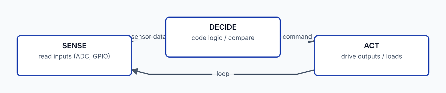
Now the embedded control loop is complete:
- Sense: digital inputs (buttons, digital sensors) + analog inputs (ADC for varying sensors). The full picture of what's happening.
- Decide: the code's logic processes the inputs.
- Act: digital outputs (on/off, via transistors for real loads) + PWM (proportional control — brightness, speed). The full range of actions.
A real project — say, an automatic plant waterer — reads soil moisture (analog input + ADC), checks it against a threshold (decide), and runs a pump (digital output → transistor → pump, with a flyback diode). Every capability and every ladder rung in one device.
The next lesson covers choosing the right microcontroller (ESP32 vs Arduino vs Pi), the development cycle, and a complete L0–L4 project that integrates everything.
To read a potentiometer's position (a varying voltage), you use a pin's: