ESP32 vs Arduino vs Raspberry Pi: which when
Three platforms cover most projects: the ESP32, the Arduino, and the Raspberry Pi. Choosing the right one is a recurring decision.
ESP32 — the connected workhorse
The ESP32 (and its variants: DevKitC, S3, CAM) is a powerful microcontroller with built-in Wi-Fi and Bluetooth.
Strengths:
- Wi-Fi + Bluetooth integrated — the standout feature. Perfect for IoT, connected sensors, anything that talks to a network or phone.
- Powerful — dual-core, hundreds of MHz, plenty of RAM/flash. Handles demanding tasks.
- Low-power modes — deep-sleep modes that drop power consumption dramatically, enabling battery-powered connected devices that last.
- Rich peripherals — many GPIO, multiple ADC channels, PWM, all the communication interfaces, touch sensing.
Best for:
- Connected (IoT) projects — sensors that report over Wi-Fi, devices controlled from a phone.
- Battery-powered connected devices (the deep-sleep modes make this viable).
- Projects needing more compute than an Arduino offers.
The catalog default for connected projects. When a customer's project mentions Wi-Fi, remote monitoring, or phone control, the ESP32 is usually the answer.
Arduino — the simple, beginner-friendly choice
The Arduino (Uno, Nano) is a simpler microcontroller with a huge community and ecosystem.
Strengths:
- Beginner-friendly — the most documented, tutorialed, supported platform. If you're stuck, someone has solved your problem online.
- Simple — straightforward, predictable, no unnecessary complexity.
- Robust ecosystem — countless libraries, shields (add-on boards), and examples.
- Forgiving — the Uno runs at 5V (more tolerant), is hard to damage, great for learning.
Limitations:
- No Wi-Fi/Bluetooth (on the basic Uno/Nano) — add-on modules needed for connectivity.
- Less powerful — slower, less memory than an ESP32. Fine for simple tasks, limiting for demanding ones.
Best for:
- Simple projects — read a few sensors, drive some outputs, no connectivity needed.
- Learning — the ideal first microcontroller.
- Projects where the huge community support matters most.
The catalog default for simple, no-connectivity, beginner projects. When a customer is starting out or building something simple without Wi-Fi, the Arduino is usually the right call.
Raspberry Pi — the full computer (a different category)
The Raspberry Pi is a full single-board computer running Linux — not really a microcontroller at all.
Strengths:
- Powerful — a real computer, runs a full OS, can do heavy computation, vision, machine learning, run a display.
- Versatile — programs in many languages, runs full applications, networks easily.
- Has GPIO too — so it can interface with hardware like a microcontroller (though with caveats).
Limitations:
- Power-hungry — needs significant power, not suited to battery operation like a microcontroller's deep-sleep.
- Slow to boot — runs an OS, so it takes seconds to start (a microcontroller runs instantly on power-up).
- Overkill + less robust for simple control — using a full Linux computer to blink an LED or read a sensor is wasteful and adds failure modes (SD card corruption, OS issues).
- Not real-time — the OS can introduce timing unpredictability that matters for precise control.
Best for:
- Compute-heavy tasks — camera/vision processing, machine learning, running a graphical interface.
- Projects needing a full OS, networking stack, or significant processing.
- When you genuinely need a computer, not a microcontroller.
Not the default for simple control. For sensing and switching, a microcontroller (ESP32/Arduino) is simpler, cheaper, lower-power, and more robust. Reach for the Pi only when you need real computing power.
The selection logic
| Project needs | Choose |
|---|---|
| Wi-Fi/Bluetooth, IoT, phone control | ESP32 |
| Battery + connectivity | ESP32 (deep-sleep) |
| Simple, no connectivity, learning | Arduino (Uno/Nano) |
| Maximum community support | Arduino |
| Heavy compute, vision, ML, a display, full OS | Raspberry Pi |
| Real-time precise control | Microcontroller (ESP32/Arduino), not Pi |
A useful mental flowchart:
- Need heavy compute / vision / a screen / full OS? → Raspberry Pi.
- Else, need Wi-Fi/Bluetooth? → ESP32.
- Else (simple, no connectivity)? → Arduino.
Choosing honestly
When someone asks "which board should I use?", the honest recommendation follows a simple pattern:
- Qualify the project (what are they building? connectivity? power? complexity?).
- Recommend the genuine fit — ESP32 for connected, Arduino for simple, Pi for compute-heavy.
- Name the trade-offs honestly (the ESP32 is more capable but slightly more complex; the Pi is powerful but overkill for simple control).
- Don't over-spec — recommend the simplest board that meets the requirement, not the most expensive.
A simple relay controller doesn't need an ESP32's Wi-Fi (or a Pi's Linux) — the honest choice is the Arduino. A Wi-Fi sensor genuinely needs the ESP32. The fit drives the choice.
The next slide covers the development cycle — how you actually get code onto a microcontroller and iterate.
A project needs Wi-Fi + low power for a battery sensor. The best fit is:
The development cycle: write, flash, run, debug
Getting a program onto a microcontroller and making it work follows a development cycle: write, flash, run, debug, repeat. Understanding the cycle is understanding how you actually build microcontroller projects.
The cycle
- Write the code on your computer (in a development environment).
- Compile it (the environment turns your code into the binary the chip runs — usually automatic on upload).
- Flash (upload) the compiled program to the microcontroller's flash memory, usually over USB.
- Run — the microcontroller executes your program (immediately after flashing, and every time it powers on).
- Observe / debug — watch what it does; use serial output to see what's happening inside.
- Repeat — fix, improve, re-flash.
This loop — write, flash, run, debug — is how every microcontroller project is built, iteratively.
Writing code: the development environment
You write microcontroller code in an IDE (Integrated Development Environment):
- Arduino IDE — the beginner standard. Simple, supports Arduino and (with board packages) the ESP32. Big library ecosystem.
- PlatformIO — a more powerful environment (a VS Code extension), popular for larger projects, supporting many boards.
- Others exist (Espressif's ESP-IDF for advanced ESP32 work, etc.).
For most makers and learners, the Arduino IDE is where you start — it handles the ESP32 and Arduino boards, has a vast library collection, and is beginner-friendly.
The language
Microcontroller code is typically written in C/C++ (the Arduino framework is C++ with helpful libraries). The Arduino framework gives you simple functions:
pinMode(pin, OUTPUT)— configure a pin's direction.digitalWrite(pin, HIGH)— drive a digital output.digitalRead(pin)— read a digital input.analogRead(pin)— read an analog input (ADC).analogWrite(pin, value)— PWM output.delay(ms)— wait.
A blink program (the "hello world" of microcontrollers):
void setup() {
  pinMode(13, OUTPUT);   // pin 13 is an output
}
void loop() {
  digitalWrite(13, HIGH);  // LED on
  delay(500);              // wait 0.5s
  digitalWrite(13, LOW);   // LED off
  delay(500);              // wait 0.5s
}
setup() runs once at power-up; loop() runs over and over forever. This structure — setup once, then loop — is the Arduino framework's model, and it maps naturally to the sense-decide-act loop.
Flashing: uploading to the chip
To flash:
- Connect the board to your computer via USB.
- Select the board type and port in the IDE.
- Click upload — the IDE compiles your code and sends it to the chip's flash memory.
- The chip resets and runs the new program.
On a development board, the USB connection handles everything — power, flashing, and serial communication for debugging. This is why dev boards are so convenient: plug in USB, write code, click upload, watch it run.
The flashed program persists in flash memory — unplug and replug the board (or power it from any source) and it runs the same program. No computer needed once flashed. (This is the difference from a Raspberry Pi, which boots an OS from an SD card; a microcontroller runs its single flashed program directly.)
Debugging: seeing what's happening
When your program doesn't work as expected (it won't, at first — that's normal), you debug. The main tool:
- Serial output. Your code can print messages over the USB connection (
Serial.print()in Arduino), and you view them in the IDE's "Serial Monitor." This lets you see variable values, track which code ran, and find where things go wrong. It's the microcontroller equivalent of "print debugging."
Other debugging approaches: blinking an LED to signal state, using a multimeter (L0) to check voltages, an oscilloscope or logic analyzer for signals. But serial output is the everyday workhorse — sprinkle Serial.print() statements to see what your code is doing.
The iterative reality
Real development is iterative — you rarely get it right the first time:
- Write a first version, flash it.
- It doesn't quite work (the LED doesn't blink, the sensor reads wrong).
- Add serial output to see what's happening.
- Spot the problem (a floating input, a wrong pin, a logic error).
- Fix it, re-flash.
- Repeat until it works.
This cycle is fast — flashing takes seconds — so you iterate quickly. The skill of debugging (forming a hypothesis about what's wrong, checking it with serial output or a multimeter, fixing, re-testing) is as important as writing the code in the first place.
Common first-project issues
The bugs you'll hit early (and their ladder connections):
- A button reads randomly → floating input (L1/L3) — add a pull resistor or enable the internal pull-up.
- An LED doesn't light → wrong pin, missing current-limit resistor (L1), backwards LED (L2 polarity), or the pin not set as output.
- A motor doesn't run / the chip resets → driving the load directly instead of through a transistor (L2), or an inadequate power supply.
- Garbled serial output → wrong baud rate (a serial-communication setting — L5 territory).
- Nothing happens at all → not powered, not flashed correctly, or a wiring error.
Each of these connects to a ladder concept. The debugging skill is recognizing the symptom and tracing it to the cause — which is exactly why you climbed L0–L3 before getting here: the microcontroller's behaviour rests on all those foundations, and debugging it means understanding them.
The final slide brings it all together: a complete project that integrates every rung of the Technical Ladder, L0 through L4.
The complete picture: L0-L4 in one project
A complete microcontroller project integrates every rung of the Technical Ladder, L0 through L4. Walking through one project shows how the whole foundation comes together — and why you climbed each rung.
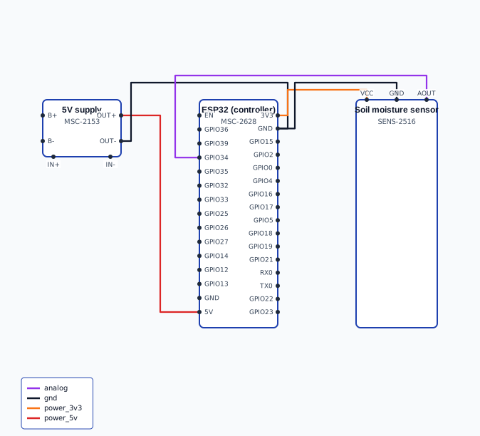
The project: an automatic plant watering system
A simple but complete project: water a plant automatically when the soil gets dry. It uses every concept you've learned.
What it does:
- Reads a soil moisture sensor.
- If the soil is too dry, runs a small water pump for a few seconds.
- Repeats periodically.
The components:
- An ESP32 or Arduino (the microcontroller).
- A capacitive soil moisture sensor (analog output).
- A small 12V water pump.
- A logic-level MOSFET to switch the pump.
- A flyback diode (the pump is inductive).
- Supporting passives: the sensor's connections, the MOSFET's gate resistor + pull-down, decoupling capacitors.
- A 12V supply for the pump; the microcontroller on its own 3.3V/5V.
How every ladder rung appears
L0 — Fundamentals:
- Units + datasheets: you read the sensor's, the MOSFET's, and the pump's specs to choose and connect them correctly (the pump's current, the MOSFET's ratings, the sensor's voltage).
- Power: the 12V pump supply + the microcontroller's supply, both correct, with a common ground.
- Soldering: if you build it on a perfboard or custom PCB, the joints (the L0 lab skill).
L1 — Passives:
- Decoupling capacitors on the microcontroller's power pins — keeping it stable.
- The MOSFET's gate resistor + pull-down — robust switching.
- The voltage handling if the moisture sensor's output needs scaling for the ADC range.
- Capacitor smoothing on the pump's supply if needed.
L2 — Diodes & Transistors:
- The MOSFET switches the pump (the microcontroller can't drive a pump directly — the GPIO current limit).
- The flyback diode across the pump protects the MOSFET from the inductive kick when the pump switches off.
- This is the microcontroller-drives-a-load pattern in action.
L3 — Digital & Logic:
- The ADC converts the moisture sensor's analog voltage to a number the code reads.
- The digital logic of the decision (is the moisture below the threshold?).
- The binary representation of the sensor reading and the threshold.
L4 — Microcontroller:
- The microcontroller runs the program: read the sensor (analog input/ADC), decide (compare to threshold), act (drive the MOSFET to run the pump).
- GPIO for the sensor input and the pump-control output.
- The development cycle — you wrote, flashed, and debugged the code.
The sense-decide-act loop
The project is the embedded control loop, fully realized:
- Sense: read the moisture sensor (analog input → ADC → a number). [L1 + L3 + L4]
- Decide: is the number below the "dry" threshold? [L3 + L4 — the code's logic]
- Act: if dry, drive the MOSFET HIGH → pump runs → waters the plant. [L2 + L4]
- Wait, repeat.
Every rung of the ladder contributes. The components (L1, L2) build the circuit; the digital concepts (L3) handle the sensing and logic; the microcontroller (L4) runs it all. Remove any rung's contribution and the project fails — no decoupling and the microcontroller glitches; no transistor and you fry the GPIO; no ADC understanding and you can't read the sensor; no flyback diode and you destroy the MOSFET.
This is what "understanding electronics" means
The plant waterer isn't impressive on its own — but the fact that you understand every part of it is. You're not following a tutorial blindly; you understand:
- Why the decoupling capacitor is there (L1).
- Why the pump needs a MOSFET and a flyback diode (L2).
- How the moisture reading becomes a number (L3).
- How the microcontroller ties it together (L4).
- Why each component is rated as it is (L0).
That complete understanding is the difference between copying a circuit and engineering one. It's what lets you debug when something goes wrong, adapt the design to new requirements, and build things that aren't in any tutorial.
Where the ladder goes from here
L0–L4 is the foundation of foundational electronics — the components, the digital world, and the microcontroller that integrates them. From here, the Technical Ladder continues:
- L5 — Interfacing & Communication: how the microcontroller talks to sensors and other devices (UART, SPI, I²C) — the communication interfaces mentioned throughout.
- L6 — Power Systems & Solar: the deep dive into power — batteries, charging, solar, the heart of solar power systems.
- L7 — Test & Measurement: using the bench instruments (multimeter, oscilloscope) to measure and debug properly.
- L8 — Mechanical & Fabrication: enclosures, 3D printing and prototyping.
- L9 — Product Portfolio Mastery: deep product knowledge — what to recommend when.
- L10 — Integration Capstone: a complete product, integrating everything.
Each builds on L0–L4. The components and microcontroller foundation you've now completed underlies all of it.
The L4 + L0–L4 summary
L4 (Microcontrollers):
- A microcontroller is a complete computer on a chip — CPU, memory, peripherals — built to control hardware via software.
- GPIO is the interface: digital I/O (read buttons, drive LEDs/transistors), analog input (ADC), PWM output.
- The current limit means real loads need a transistor (the L2 pattern).
- Choose ESP32 (connected), Arduino (simple/learning), or Raspberry Pi (heavy compute) by fit.
- The development cycle is write → flash → run → debug → repeat.
L0–L4 (the foundation):
- L0: fundamentals (units, schematics, datasheets, safety, soldering).
- L1: passives (R, C, L, and their circuits).
- L2: active components (diodes, transistors — steering, switching, amplifying).
- L3: digital & logic (binary, gates, the analog-digital bridge).
- L4: the microcontroller — integrating it all into a programmable device that senses, computes, and controls.
You've completed the foundational electronics of the Technical Ladder. You understand what's inside the products in this domain, you can build and debug real microcontroller projects, and you have the foundation for everything above L4. The components, the logic, and the microcontroller — the building blocks of every electronic system — are now yours.