The microcontroller: a computer on a chip
A microcontroller is a complete small computer on a single chip — a CPU, memory, and hardware-control peripherals all integrated together. It's the programmable brain at the heart of nearly every modern electronic product, and the device that ties together everything you've learned in the Technical Ladder.
A computer built to control hardware
You're familiar with computers — laptops, phones. A microcontroller is a computer too, but a special kind:
- Tiny + cheap. A microcontroller might cost a dollar or two and fit on a fingernail.
- Self-contained. Everything it needs — processor, memory, and peripherals — is on the one chip. It doesn't need a motherboard full of supporting chips like a desktop CPU does.
- Built to control hardware. Its whole purpose is interfacing with the physical world — reading sensors, switching outputs, talking to other devices. A desktop CPU targets general computing (running apps, displaying graphics); a microcontroller targets control.
When you flip a switch and an LED responds, when a thermostat reads temperature and turns on a fan, when a solar charge controller manages a battery — there's almost always a microcontroller running a program that senses, decides, and acts.
Why a microcontroller, not just logic gates?
L3 showed you logic gates and how they build digital systems. You could build a controller from discrete logic gates — and decades ago, people did. But a microcontroller is far better for most jobs because it's programmable:
- Logic gates are fixed. Once wired, a gate circuit does one thing. To change its behaviour, you rewire it.
- A microcontroller is reprogrammable. Its behaviour is defined by software — code stored in its memory. Change the code, change what it does, without touching the wiring.
This programmability is transformative. The same physical chip can be a thermostat, a light controller, a motor driver, a data logger — just by loading different code. You design the hardware once and define the behaviour in software. That flexibility is why microcontrollers replaced custom logic in nearly every application.
Common microcontroller platforms
The microcontrollers most makers and engineers use:
- ESP32 (and variants — DevKitC, S3, CAM): a powerful microcontroller with built-in Wi-Fi and Bluetooth. The go-to for connected (IoT) projects.
- ESP8266: a simpler Wi-Fi microcontroller (the ESP32's predecessor).
- Arduino (Uno, Nano): beginner-friendly microcontrollers with a huge community and ecosystem. Great for learning and simple projects.
(The Raspberry Pi, also widely available, is a full single-board computer running Linux — more powerful but a different category, covered in Lesson 3.)
Which one to choose depends on the project — Wi-Fi needs, power constraints, complexity. Lesson 3 covers the selection. For now, know that these are the programmable brains you'll build projects around.
The microcontroller integrates the whole ladder
This is why L4 is the capstone of L0–L4. A microcontroller brings together everything:
- It's built from transistors (L2) forming logic gates (L3) forming a processor — the abstraction stack you climbed.
- It reads the analog world through its ADC (L3) — sensors, voltages (often via a divider, L1).
- It drives outputs through GPIO pins that switch transistors (L2) to control real loads.
- It's a digital system (L3) running on a clock, executing your code.
- It needs a properly built circuit (L0) — power, ground, decoupling capacitors (L1).
A microcontroller project is the Technical Ladder integrated into one working system. Understanding the microcontroller means understanding how all the pieces — components, logic, computation — come together to control the physical world.
What's coming in L4
- This lesson: what a microcontroller is — its internals (CPU, memory, peripherals) and the basic circuit it needs to run.
- Lesson 2: GPIO — how the microcontroller talks to the world: digital I/O, the current-limit + driving-loads pattern, and analog input + PWM output.
- Lesson 3: choosing + using a microcontroller — ESP32 vs Arduino vs Pi, the development cycle, and the complete L0–L4 project.
By the end, you'll understand what a microcontroller is, how to interface it with the world, how to choose the right one, and how it integrates everything you've learned. The next slide opens the chip up — what's inside a microcontroller.
CPU, memory, peripherals — what's inside
Inside a microcontroller are four main parts: the CPU (runs the code), program memory (stores the code), data memory (holds working values), and peripherals (interface with hardware). Understanding what's inside demystifies the chip.
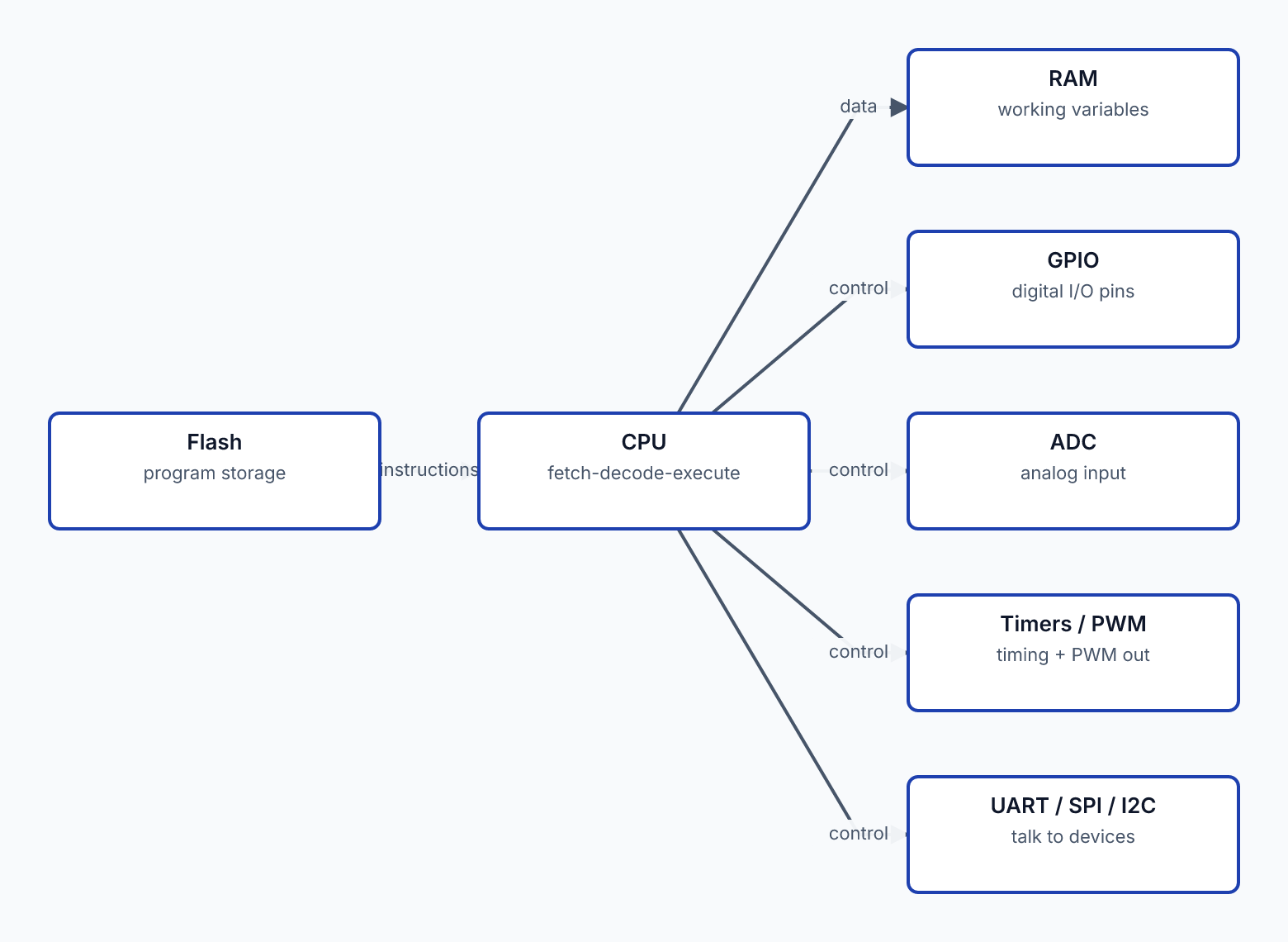
The CPU (processor)
The CPU is the part that executes your program — fetching instructions and carrying them out, one after another (the fetch-decode-execute cycle from L3's sequential logic). It's the "thinking" part.
- It runs at a clock speed (L3) — an ESP32 might run at 80–240MHz, an Arduino Uno at 16MHz.
- It does the arithmetic and logic your code specifies (add these numbers, compare these values, decide this branch).
- It's built from the logic gates of L3, which are built from the transistors of L2.
The CPU is general-purpose: it does whatever your program tells it. The program is what makes the microcontroller a thermostat vs a light controller vs a data logger.
Program memory (flash)
Your code has to be stored somewhere so the microcontroller can run it. That's flash memory — non-volatile storage that keeps the program even when power is off.
- You "flash" (upload) your compiled program into this memory (the development cycle, Lesson 3).
- On power-up, the CPU starts executing the program from flash.
- It persists — power-cycle the chip and it runs the same program again. (This is why a flashed Arduino runs its program every time you plug it in, no computer needed.)
Flash sizes vary: an Arduino Uno has ~32KB; an ESP32 has several MB. More flash = room for bigger programs.
Data memory (RAM)
While the program runs, it needs working space for variables, calculations, and temporary data. That's RAM — fast, volatile memory (cleared on power-off).
- Your program's variables live here while it runs.
- It's the "scratchpad" the CPU uses during computation.
- It's volatile — power off and it's gone (unlike flash, which keeps the program).
RAM is smaller than flash and precious on microcontrollers (an Uno has ~2KB; an ESP32 has hundreds of KB). Efficient memory use matters in embedded programming — you can't be wasteful with RAM the way you might on a desktop.
Peripherals (the hardware interfaces)
This is what makes a microcontroller special vs a plain CPU — integrated peripherals that interface with the physical world:
- GPIO (General-Purpose Input/Output): the configurable pins that read and drive signals. (Lesson 2 covers these in depth.)
- ADC (Analog-to-Digital Converter): reads analog voltages (L3) — sensors, potentiometers.
- Timers / PWM: for timing, generating PWM signals (L3), measuring intervals.
- Communication interfaces (UART, SPI, I²C): for talking to other chips and devices (L5 covers these).
- Sometimes more: DAC, touch sensing, Wi-Fi/Bluetooth radios (ESP32), etc.
These peripherals are why a microcontroller can directly sense and control hardware. A desktop CPU has none of this built in — it needs external chips for everything. The microcontroller's integrated peripherals are its defining feature.
The integration is the point
A desktop computer spreads these parts across many chips: a CPU, separate RAM sticks, a storage drive, and various interface chips on the motherboard. A microcontroller integrates the CPU, memory, and peripherals onto one chip. That integration is what makes it:
- Small (one chip, not a board full of chips).
- Cheap (one part to buy).
- Reliable (fewer connections to fail).
- Easy to design with (the chip + minimal supporting components = a working system).
When a datasheet describes a microcontroller, it's describing all of this: the CPU's speed and architecture, the flash and RAM sizes, and the list of peripherals (how many GPIO, how many ADC channels, what communication interfaces). Reading those specs tells you what the chip can do.
What you actually interact with
As someone building projects, you mostly interact with:
- The GPIO pins — wiring up your inputs and outputs.
- The peripherals — using the ADC to read a sensor, PWM to dim an LED, I²C to talk to a sensor module.
- The memory — being mindful of flash (program size) and RAM (variable space).
- The code — which the CPU runs.
You don't usually think about the transistors and gates inside (L2/L3) — but knowing they're there, and that the chip is a real computer following the principles you've learned, makes the microcontroller comprehensible rather than magical.
The next slide covers the basic circuit a microcontroller needs to run — power, ground, and the supporting components (the L0/L1 essentials) that any microcontroller circuit requires.
What distinguishes a microcontroller from a desktop CPU?
Powering + the basic circuit a microcontroller needs
A microcontroller needs a few things to run: stable power, ground, decoupling capacitors, and a way to load the program. When you use a development board (Arduino, ESP32 DevKit), most of this is handled for you — but understanding what's needed explains why those boards are designed as they are.
Power + ground
Every microcontroller needs a clean, correct power supply:
- The right voltage. ESP32 and most modern microcontrollers run on 3.3V. Arduino Uno runs on 5V (with an onboard regulator accepting higher input). Apply the wrong voltage — too high — and you damage the chip. Always confirm the operating voltage (L0's datasheet skill).
- Ground. A common ground reference for the whole circuit. Every signal voltage is measured relative to ground; without a shared ground, nothing works correctly (recall L2's common-ground requirement for driving loads).
- Adequate current. The supply must deliver enough current for the microcontroller plus whatever it's driving. An ESP32 transmitting Wi-Fi draws current spikes that a weak supply can't handle — causing brownouts and resets.
Decoupling capacitors (L1)
A microcontroller, like any digital chip, needs decoupling capacitors on its power pins (from L1):
- A small ceramic (typically 100nF) close to each power pin handles the fast current demands as the chip switches internally.
- Often a larger capacitor (a few µF or more electrolytic) nearby for bulk smoothing.
Without decoupling, the chip's power dips on every internal switching event (millions per second), causing glitches, random resets, and unreliable behaviour. This is the L1 decoupling concept applied to the microcontroller — and one reason a flaky microcontroller circuit often just needs proper decoupling.
On a development board, these capacitors are already on the board. On a bare chip (designing your own PCB), you add them yourself — it's one of the non-negotiables of a microcontroller circuit.
The clock source (L3)
A microcontroller needs a clock (L3) to pace its operation:
- Many microcontrollers have an internal oscillator — a built-in clock source, no external parts needed. Convenient for simple uses.
- Some use an external crystal for a more precise clock (the 16MHz crystal on an Arduino Uno). Precision matters for accurate timing and reliable communication.
On a development board, the clock source is included. The clock is what steps the CPU through your program (L3's sequential logic) — without it, the chip is frozen.
Loading the program (the flashing interface)
You need a way to get your compiled program into the chip's flash memory:
- Most development boards include a USB interface that handles flashing — plug in USB, upload from your computer, done.
- Bare chips use a programming interface (various protocols) requiring a programmer device or a bootloader.
Development boards make this trivial: the USB port both powers the board and flashes the program. This is a big reason beginners start with development boards rather than bare chips — the flashing (and power, and clock, and decoupling) is all handled.
Reset + boot pins
Microcontrollers have a reset pin (to restart the chip) and sometimes boot-mode pins (to enter programming mode):
- The reset pin restarts the program from the beginning — useful for recovery, often a button on dev boards.
- Boot pins (on the ESP32, for example) select whether the chip boots normally or enters flashing mode. Dev boards usually handle this automatically during upload, but on bare designs you manage it.
These are details you'll meet when you go beyond dev boards to custom designs; on a dev board, they're handled.
The development board: everything handled
This is why development boards (Arduino Uno, ESP32 DevKitC) are how everyone starts:
A dev board packages the microcontroller chip + power regulation + decoupling + clock + USB flashing + reset button + broken-out GPIO pins (often with a USB-to-serial chip for debugging output). You get a working, ready-to-program microcontroller system — just plug in USB and start coding.
The bare chip (for a custom PCB) requires you to provide all of this yourself: the right voltage regulator, the decoupling capacitors, the clock (or rely on internal), the flashing interface, the reset/boot circuitry. That's the step from "using a dev board" to "designing a product" — covered later in the ladder and in real product design work (a BOM for a custom board includes all these supporting parts).
The minimal circuit summary
A microcontroller needs:
- Correct, stable power at the right voltage (3.3V or 5V).
- Common ground.
- Decoupling capacitors (L1) on the power pins.
- A clock (internal or external crystal).
- A way to flash the program.
- Reset/boot handling.
On a dev board: all included. On a bare chip: you provide it. Either way, these are the essentials — the L0 (power, datasheet) and L1 (decoupling) foundations applied to make a microcontroller actually run.
The next lesson is the heart of using a microcontroller: GPIO — how it reads inputs and drives outputs to interact with the physical world.