The basic gates: AND, OR, NOT
Logic gates are the building blocks of digital computation. Each gate takes one or more binary inputs and produces a binary output according to a simple rule. The three fundamental gates — AND, OR, NOT — combine to build every digital circuit, up to and including the microcontroller.
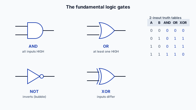
AND gate
An AND gate outputs HIGH (1) only when ALL its inputs are HIGH.
Truth table (2-input AND):
| A | B | Output |
|---|---|---|
| 0 | 0 | 0 |
| 0 | 1 | 0 |
| 1 | 0 | 0 |
| 1 | 1 | 1 |
In words: "the output is 1 only if A AND B are both 1." Any 0 input forces the output to 0.
Everyday analogy: a safety interlock — the machine runs (output 1) only if the guard is closed AND the start button is pressed. Both conditions required.
OR gate
An OR gate outputs HIGH (1) when AT LEAST ONE input is HIGH.
Truth table (2-input OR):
| A | B | Output |
|---|---|---|
| 0 | 0 | 0 |
| 0 | 1 | 1 |
| 1 | 0 | 1 |
| 1 | 1 | 1 |
In words: "the output is 1 if A OR B (or both) is 1." Only all-0 inputs give a 0 output.
Everyday analogy: an alarm that triggers (output 1) if the front door OR the back door is opened. Either one is enough.
NOT gate (inverter)
A NOT gate has one input and outputs its opposite.
Truth table:
| A | Output |
|---|---|
| 0 | 1 |
| 1 | 0 |
In words: "the output is the inverse of the input." HIGH becomes LOW, LOW becomes HIGH.
Everyday analogy: a "not-ready" indicator that's ON (1) when the system is NOT ready (0).
Why these three are enough
AND, OR, and NOT together are functionally complete — any digital logic function whatsoever can be built from combinations of these three. Want a circuit that does something complicated? It can be expressed as some arrangement of ANDs, ORs, and NOTs.
This is a profound idea: all of digital computation, no matter how complex, reduces to combinations of these three simple operations. A microcontroller running your code is, at the hardware level, millions of these gates arranged to compute.
Gates have standard symbols
Each gate has a schematic symbol you'll learn to recognize:
- AND: a D-shape (flat back, curved front).
- OR: a curved-back shield shape with a pointed front.
- NOT: a triangle with a small circle (bubble) at the output — the bubble means "invert."
- The bubble is key: a small circle on any gate's output means "invert the output."
You don't need to memorize the exact shapes right now, but recognizing that a symbol represents a logic operation — and that a bubble means inversion — is part of reading digital schematics.
Gates in the real world
You can buy logic gates as discrete chips (the classic 7400-series: a 7408 is four AND gates, a 7432 is four OR gates, a 7404 is six inverters). These were how digital circuits were built before microcontrollers — wiring gates together to make logic.
Today, most logic lives inside chips (microcontrollers, FPGAs) rather than as discrete gate chips on a board. But the concept is unchanged: the chip's internals are gates, and understanding gates is understanding what the chip does at its foundation. Occasionally you'll still use a discrete gate chip for simple glue logic (combining a couple of signals).
What's coming
The next slide covers the derived gates — NAND, NOR, XOR — and how truth tables fully describe any logic. Then the final slide of this lesson reveals how gates are built from the transistors you learned in L2 — closing the loop from components to computation.
An AND gate outputs HIGH (1) when:
NAND, NOR, XOR + truth tables
Beyond the three fundamental gates, a few derived gates appear constantly: NAND, NOR, and XOR. And the truth table — which fully describes any logic — is the tool for understanding and designing logic circuits.
NAND gate (NOT-AND)
A NAND gate is an AND followed by a NOT — it outputs the inverse of AND. Output is LOW only when ALL inputs are HIGH; otherwise HIGH.
Truth table (2-input NAND):
| A | B | Output |
|---|---|---|
| 0 | 0 | 1 |
| 0 | 1 | 1 |
| 1 | 0 | 1 |
| 1 | 1 | 0 |
The output is the opposite of the AND gate. NAND has a special property: it's universal — you can build ANY logic function (AND, OR, NOT, everything) using only NAND gates. This makes NAND a favourite in chip manufacturing; entire processors can be (and are) built from NAND gates alone.
NOR gate (NOT-OR)
A NOR gate is an OR followed by a NOT — the inverse of OR. Output is HIGH only when ALL inputs are LOW.
Truth table (2-input NOR):
| A | B | Output |
|---|---|---|
| 0 | 0 | 1 |
| 0 | 1 | 0 |
| 1 | 0 | 0 |
| 1 | 1 | 0 |
NOR is also universal (any logic from NOR alone). NAND and NOR are the workhorse gates of real chip design because of this universality + efficiency in manufacturing.
XOR gate (exclusive-OR)
XOR outputs HIGH when its inputs are different — one HIGH and one LOW, but not both.
Truth table (2-input XOR):
| A | B | Output |
|---|---|---|
| 0 | 0 | 0 |
| 0 | 1 | 1 |
| 1 | 0 | 1 |
| 1 | 1 | 0 |
"One or the other, but not both." XOR is special:
- Addition: XOR computes the sum bit in binary addition (1+1 = 0 carry 1; the sum bit is XOR, the carry is AND). It's at the heart of how computers add.
- Parity / error detection: XOR of a set of bits tells you if there's an even or odd number of 1s — used in error-checking.
- Comparison: XOR outputs 1 when bits differ, useful for detecting changes.
Truth tables describe any logic
A truth table lists every possible input combination and the output for each. It completely and unambiguously describes a logic function:
- 2 inputs → 4 rows (2² combinations).
- 3 inputs → 8 rows (2³).
- n inputs → 2ⁿ rows.
The truth table is the design tool for combinational logic. If you can write down what output you want for every input combination, you've defined the logic — and there are systematic methods (Boolean algebra, Karnaugh maps — later in the ladder) to turn a truth table into a gate circuit.
Reading a truth table
To use a truth table:
- Find the row matching your current inputs.
- Read the output for that row.
For example, a 3-input "majority" circuit (output HIGH when 2 or more inputs are HIGH) has a truth table with 8 rows; the output is 1 in the rows where at least two inputs are 1. The truth table fully specifies it, and from the table you can derive the gate arrangement.
Combining gates
Real logic combines gates. A simple example: "the output is HIGH when (A AND B) OR (NOT C)." This uses an AND gate (A, B), a NOT gate (C), and an OR gate combining them. The truth table for this combined logic has 8 rows (3 inputs), and you can work out each row by evaluating the expression.
Combinational logic — gates combined to compute an output purely from the current inputs — is the foundation. Lesson 3 covers combining gates into useful circuits, then the leap to sequential logic (where the output also depends on past state, via memory + clocks).
The gates you'll actually use
In modern embedded work, you rarely wire individual gate chips — the logic lives inside microcontrollers and other ICs. But:
- You'll read logic in datasheets and schematics (a chip's logic described by gates/truth tables).
- You'll think in logic (a condition that's true when A AND B but NOT C — that's logic, even when you write it in code).
- You'll occasionally use a discrete gate for simple glue logic.
And understanding that the microcontroller's internals ARE gates — millions of them — demystifies what the chip is doing.
The next slide reveals how these gates are physically built from the transistors you learned in L2 — the bridge from components to computation.
An XOR (exclusive-OR) gate outputs HIGH when:
Gates are built from transistors
Here's the connection that ties the whole Technical Ladder together: logic gates are built from transistors — the same switches you learned in L2. The binary world of L3 sits directly on top of the components of L2.
A gate is just transistors arranged cleverly
Every logic gate is a small arrangement of transistors that produces the gate's input-output behaviour. The transistor's switching property (L2) — a control input governs whether current flows — is exactly what's needed to implement logic.
Consider the simplest case, the NOT gate (inverter), built from a single transistor:
- A transistor (say an N-channel MOSFET) with its gate as the input, its drain connected to the supply through a resistor (a "pull-up"), and the output taken from the drain.
- Input LOW: transistor off → no current → the pull-up resistor pulls the output HIGH. Output = inverse of input. ✓
- Input HIGH: transistor on → conducts to ground → output pulled LOW. Output = inverse of input. ✓
A single transistor + a resistor inverts the signal. That's a NOT gate — built from L2 components.
NAND and NOR from a few transistors
More complex gates use a few transistors. A NAND gate (in CMOS, the dominant technology) uses four transistors arranged so the output goes LOW only when both inputs are HIGH. A NOR similarly. The exact arrangements aren't critical to memorize — the point is:
A handful of transistors → a logic gate.
And since NAND (or NOR) is universal, and gates combine into any logic, you can build everything from transistors:
Transistors → gates → logic circuits → the microcontroller.
The CMOS technology
Modern digital chips use CMOS (Complementary Metal-Oxide-Semiconductor) — gates built from complementary pairs of N-channel and P-channel MOSFETs. CMOS is dominant because it's extremely efficient: a CMOS gate draws almost no power when static (not switching), only consuming energy during transitions. This is why your microcontroller can run on tiny currents — its millions of CMOS gates sip power only when switching.
(This connects to L2's MOSFET efficiency: the MOSFET's near-zero static current is exactly what makes CMOS logic low-power. The component property enables the system property.)
The scale of it
A logic gate is a few transistors. A microcontroller contains:
- Millions to billions of transistors, arranged into millions of gates.
- Those gates form the processor core, the memory, the peripherals.
- All running on the binary logic of L3, built from the transistor switches of L2.
When you set a microcontroller pin HIGH in your code (L4), you're ultimately switching transistors that drive the pin to the supply voltage. The whole stack — from your line of code down to the physical transistor — is what you've been building up through the ladder.
Why this matters
Understanding that the digital world is built from transistors does two things:
-
Demystifies the microcontroller. It's not magic — it's a vast, organized collection of the transistor switches you already understand, arranged into gates, arranged into logic, arranged into a computer. Complex, but built from simple, knowable pieces.
-
Explains the constraints. Why does logic have voltage levels? Because gates are transistors driven to supply or ground. Why does CMOS use little power? Because the MOSFETs draw current only when switching. Why are there logic-level compatibility issues? Because different chips use different supply voltages for their transistors. The system behaviour follows from the component physics.
The ladder so far
You've now climbed:
- L0: the fundamentals — units, schematics, datasheets, safety, soldering.
- L1: the passives — resistors, capacitors, inductors, and the circuits they form.
- L2: the active components — diodes (steering, protecting) and transistors (switching, amplifying).
- L3 (here): how transistors combine into the gates and logic of the digital world.
Each rung builds on the last. The transistor switch of L2 becomes the gate of L3. The gate of L3 becomes the microcontroller of L4. Understanding this progression — components to logic to computer — is what turns "I can use a microcontroller" into "I understand what a microcontroller is."
The next lesson covers the step from individual gates to digital systems: combining gates into useful logic, the role of clocks and memory (sequential logic), and the analog-to-digital bridge where the real world enters the binary one.