Combining gates: simple combinational logic
Individual gates become useful when combined. Combinational logic — gates wired together to compute an output from the current inputs — is the first level of digital system-building. It's how simple decisions and operations are implemented in hardware.
Combinational logic
"Combinational" means the output depends only on the current combination of inputs — no memory of the past. Wire gates together and the output is a pure function of what the inputs are right now.
A simple example: a circuit that turns on a warning light when a tank is too full OR too hot, but only if the system is enabled.
- Inputs:
full,hot,enabled. - Logic:
warning = enabled AND (full OR hot). - Gates: an OR gate (full, hot) feeding an AND gate (with enabled).
The truth table has 8 rows (3 inputs); the output is 1 only in rows where enabled is 1 AND at least one of full/hot is 1. Wire an OR gate into an AND gate and you've built it.
Building blocks from gates
Gates combine into standard building blocks used throughout digital systems:
-
Adders. Combining XOR (sum) and AND (carry) gates builds a circuit that adds binary numbers. Chaining adders adds multi-bit numbers — the arithmetic core of a processor.
-
Multiplexers (MUX). A circuit that selects one of several inputs to pass to the output, based on a "select" signal. Like a digital switch choosing which signal to route. Built from AND, OR, NOT gates.
-
Decoders. Convert a binary input to a "one-hot" output (e.g., a 3-bit input selects one of 8 output lines). Used for addressing — selecting which memory location or device to activate.
-
Comparators. Determine if two binary numbers are equal, or which is larger. Built from XOR (for equality) and more gates.
These building blocks, themselves made of gates, are the next level of abstraction — and they combine further into processors, memory, and peripherals.
The abstraction stack
This is the pattern of digital design — layers of abstraction, each built from the one below:

- Transistors (L2) — the physical switches.
- Gates (AND, OR, NOT, NAND...) — built from transistors.
- Building blocks (adders, MUXes, decoders) — built from gates.
- Functional units (ALU, registers, memory) — built from building blocks.
- The processor / microcontroller (L4) — built from functional units.
- Your code — runs on the processor.
Each layer hides the complexity of the one below. When you write code (L4), you don't think about gates — but they're there, all the way down. Understanding the stack means understanding that your high-level code ultimately switches physical transistors.
Why combinational logic isn't enough
Combinational logic computes from the present inputs — but real systems need memory. A system that counts events, remembers a state, or sequences through steps needs to know its past, not just its present inputs.
For example:
- A counter must remember its current count to increment it.
- A traffic light must remember which phase it's in to advance to the next.
- A microcontroller must remember the data in its registers between operations.
Pure combinational logic can't do this — its output depends only on current inputs, with no memory. For memory and sequencing, you need sequential logic — logic that includes state, coordinated by a clock. That's the next slide.
The everyday relevance
You'll mostly meet combinational logic as:
- Conditions in your code.
if (enabled && (full || hot))is combinational logic expressed in software. The same AND/OR/NOT, evaluated by the processor. - Datasheet logic. A chip's behaviour described by truth tables or logic equations.
- Glue logic. Occasionally wiring a couple of gates to combine signals on a board.
The deeper hardware design (building adders and processors from gates) is specialist work — but understanding that it's all gates, combining into building blocks, combining into computers, is the conceptual foundation L3 provides.
The next slide covers sequential logic — clocks, state, and memory — the addition that turns combinational logic into systems that remember and sequence.
Clocks, state, and memory (the leap to sequential logic)
Sequential logic adds memory and timing to combinational logic. With a clock to coordinate and storage to remember, digital systems can count, sequence, and hold state — the capabilities that turn logic into a computer.
The clock: the heartbeat
A clock is a regular timing signal — typically a square wave that alternates HIGH and LOW at a steady frequency. It's the heartbeat of a synchronous digital system: each clock pulse (or edge) is a moment when the system steps forward.
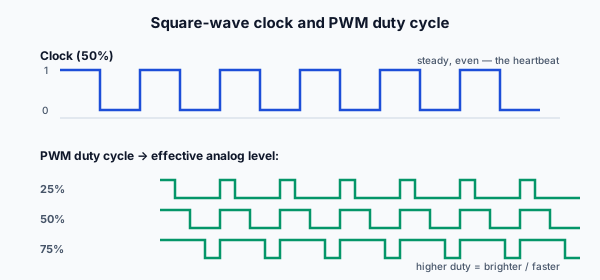
- A microcontroller running at 80MHz has a clock pulsing 80 million times per second.
- Each clock edge triggers the next step of computation — storing a result, advancing a counter, executing the next operation.
Why a clock? It synchronizes everything. Without coordination, different parts of a circuit would update at different, unpredictable times, causing chaos. The clock makes all the synchronized parts update together, in lockstep, at each edge — keeping the system orderly and predictable.
The clock frequency largely sets how fast the system runs: more clock pulses per second = more operations per second. (A microcontroller's "speed" is closely tied to its clock frequency.)
Memory: the flip-flop
The basic unit of digital memory is the flip-flop — a circuit (made of gates, made of transistors) that stores one bit. It holds its value (1 or 0) until told to change, typically on a clock edge.
- A flip-flop "remembers" one bit between clock pulses.
- Combine flip-flops and you get registers (storing a byte or word) and ultimately memory (storing thousands or millions of bytes).
This is the crucial addition: combinational logic computes from current inputs; flip-flops remember. Together — combinational logic to compute, flip-flops to store, a clock to coordinate — you have sequential logic, capable of counting, sequencing, and holding state.
Sequential logic in action
With clocks and memory, you can build:
- Counters. A register that increments by 1 on each clock edge — counting events, measuring time, generating addresses.
- State machines. A system that moves through defined states (the traffic light: green → yellow → red → green), advancing on clock edges or events. The current state is stored; the next state is computed from the current state + inputs.
- Shift registers. Storage that shifts data along on each clock — used in serial communication (sending bits one at a time) and in expanding I/O.
- Registers + RAM. The storage that holds a processor's working data and your program's variables.
These all require memory of the past (the stored state) coordinated by the clock — sequential logic, not pure combinational.
The processor as sequential logic
A microcontroller's processor is, at heart, an elaborate sequential logic system:
- On each clock cycle, it fetches the next instruction (from memory).
- Decodes it (combinational logic determines what to do).
- Executes it (combinational logic computes; results stored in registers — memory).
- Advances to the next instruction (the program counter — a register — increments).
This fetch-decode-execute cycle, stepped by the clock, repeats millions of times per second. Your program is a sequence of instructions; the processor steps through them, clock cycle by clock cycle. The registers hold the working state; the clock paces it; combinational logic does the computation at each step.
So your code running on a microcontroller (L4) is the processor's sequential logic stepping through your instructions, one clock tick at a time. The whole thing — clock, registers, fetch-decode-execute — is sequential logic, built from gates, built from transistors.
Why this matters for you
You won't design flip-flops or processors (that's deep specialist work) — but understanding sequential logic explains:
-
Why microcontrollers have a clock. Every microcontroller needs a clock source (an internal oscillator or external crystal). The clock paces everything. A "16MHz crystal" on an Arduino is its clock source.
-
Why clock speed matters. A faster clock means more operations per second — a faster microcontroller. The trade-off is power (faster = more power) and stability.
-
What "state" means in your code. When your program remembers something between iterations (a variable holding a count, a flag tracking a mode), that's stored in registers/memory — sequential logic's storage. The concept of state in software mirrors the state in hardware.
-
Timing constraints. Real digital systems have timing requirements (signals must be stable when the clock edge samples them). At the level you work, the microcontroller handles this internally, but the concept — that digital systems are paced by a clock and timing matters — underlies things like communication protocols (L5) that have clock/timing requirements.
The summary
Sequential logic = combinational logic + memory (flip-flops) + a clock to coordinate. It's the addition that lets digital systems remember and sequence — turning logic that computes from the present into systems that have state, count, and execute programs. The microcontroller is the ultimate sequential logic system: a clocked processor stepping through your instructions.
The final slide of L3 covers the analog-to-digital bridge — how the continuous real world (sensors, voltages) enters the discrete digital world the microcontroller computes in.
A clock signal in a digital system provides:
Analog-to-digital: where the real world meets the binary one
The real world is analog — temperatures, light levels, voltages all take continuous values. The microcontroller is digital — it computes in binary. The bridge between them is the Analog-to-Digital Converter (ADC), and its reverse, the Digital-to-Analog Converter (DAC). This is where the world meets the binary one.
The analog world
Most things you measure are analog:
- Temperature: a sensor outputs a voltage proportional to temperature — continuous, any value.
- Light: a light sensor's output varies smoothly with brightness.
- A potentiometer: the wiper voltage (a voltage divider, L1) varies continuously as you turn it.
- A microphone: outputs a continuously-varying voltage representing sound.
These are analog signals — continuous voltages carrying information in their exact value. The microcontroller, being digital, can't directly work with a continuous voltage; it needs a binary number.
The ADC: analog → digital
An Analog-to-Digital Converter samples an analog voltage and converts it to a binary number the microcontroller can process.
How it works (conceptually):
- The ADC measures the input voltage at an instant (a "sample").
- It compares that voltage against its range and produces a binary number representing where the voltage falls in that range.
The key specs:
-
Resolution (bits): how many binary digits the output has. A 10-bit ADC produces values 0–1023 (2¹⁰); a 12-bit ADC, 0–4095. More bits = finer resolution (smaller voltage steps distinguishable).
-
Reference voltage: the voltage range the ADC measures across. A 10-bit ADC with a 3.3V reference maps 0V → 0 and 3.3V → 1023, with each step ≈ 3.3V/1024 ≈ 3.2mV.
So reading a sensor at, say, 1.65V on a 10-bit, 3.3V ADC gives a digital value of about 512 (halfway). The microcontroller now has a number it can compute with.
The ADC connects to everything you've learned
The ADC is where L1, L2, and L3 converge:
- The voltage divider (L1) often feeds the ADC — scaling a higher voltage (a 12V battery) down to the ADC's range (3.3V) so it can be safely measured. (Reading a battery's voltage = divider + ADC.)
- Logic levels (L3) matter — the ADC's reference defines the digital scale.
- The sensor's analog output is the continuous signal; the ADC digitizes it for the microcontroller.
A huge fraction of embedded projects are: sensor → (maybe a divider) → ADC → microcontroller processes the number → acts on it. Reading a moisture sensor, a temperature, a battery level, a light level — all go through an ADC.
The DAC: digital → analog (the reverse)
A Digital-to-Analog Converter does the reverse — converts a binary number to an analog voltage. Used to:
- Generate analog signals (audio output, waveform generation).
- Set a variable voltage (a programmable reference).
DACs are less common than ADCs in simple embedded work (you read sensors more than you generate analog signals), but they're the mirror image — the microcontroller's binary number becoming a real-world voltage.
PWM: a clever digital approximation
Many microcontrollers lack a true DAC but achieve analog-like output with PWM (Pulse-Width Modulation) — rapidly switching a digital pin HIGH and LOW, varying the proportion of time it's HIGH (the "duty cycle"). Averaged out (by the load's inertia or a simple RC filter, L1), this produces an effective analog level:
- 50% duty cycle → effective half-voltage.
- 25% duty cycle → effective quarter-voltage.
PWM dims LEDs, controls motor speed, and generates rough analog signals using only digital switching. It's a digital trick that produces analog-like control — and it's everywhere in embedded work (the next rung, L4, covers using PWM from a microcontroller).
The world is analog; computation is digital
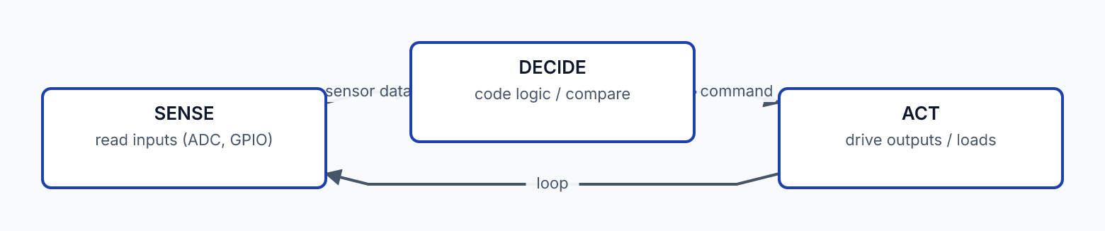
This is the big picture of L3's final concept: the world we measure and act on is analog (continuous), but computation is digital (binary). The ADC brings the analog world in; the DAC (or PWM) sends digital decisions back out. The microcontroller sits in the middle — digitizing inputs, computing in binary, producing outputs.
Every embedded system is this loop:
- Sense the analog world (sensor → ADC → number).
- Compute in the digital world (the microcontroller processes).
- Act on the world (number → DAC/PWM → analog output, or digital switching of a load via L2's transistor).
The L3 summary
Across L3:
- The binary world — HIGH/LOW, logic levels, the floating-input problem, binary numbers. The discrete two-state foundation.
- Logic gates — AND, OR, NOT, NAND, NOR, XOR; truth tables; and the revelation that gates are built from L2's transistors.
- From gates to systems — combinational logic, the abstraction stack, sequential logic (clocks + memory), and the analog-to-digital bridge.
L3 is the conceptual bridge of the Technical Ladder. It shows how the components (L1, L2) become computation, and it introduces the digital concepts — logic, binary, clocks, ADC — that the microcontroller lives in.
With L0–L3 complete, you understand the components and the digital world they build. L4 brings it together: the microcontroller — the programmable digital chip that senses (ADC), computes (sequential logic running your code), and acts (GPIO driving L2's transistors), all the concepts of the ladder integrated into one device you program to control the physical world.