HIGH and LOW: digital vs analog
Digital electronics works with just two states: HIGH and LOW, 1 and 0. This is a radical simplification from the analog world (where voltages take any value) — and that simplification is exactly what makes computation possible.
Analog vs digital
Analog signals are continuous — they can be any voltage in a range. A temperature sensor's output might be 1.37V, or 1.42V, or anything in between. The exact value carries the information. The passives (L1) and diodes/transistors (L2) you've studied so far mostly operate in this analog world.
Digital signals are discrete — they're either HIGH or LOW, with nothing meaningful in between. A digital pin is either at (roughly) the supply voltage (HIGH, 1) or at (roughly) ground (LOW, 0). The in-between region is just the brief transition; it doesn't carry information.
Why two states?
Reducing everything to two states seems limiting, but it's the key to reliable computation:
-
Noise immunity. An analog signal degrades with every bit of noise — a 1.37V reading corrupted by 0.05V of noise becomes 1.42V, a different value. But a digital HIGH corrupted by 0.05V is still clearly HIGH. As long as noise doesn't push the signal across the HIGH/LOW boundary, the information survives perfectly. Digital signals can be passed through long wires, regenerated, and copied without degradation.
-
Simple, repeatable operations. With two states, operations become logic: AND, OR, NOT. These are simple, exact, and combinable into arbitrarily complex computation. You can't easily "compute" with continuous analog values; you can with discrete digital ones.
-
Storage. Two states map naturally to storage — a bit is either set or not. Memory, registers, and the entire concept of stored data rest on this binary foundation.
The two states are voltages
Crucially, HIGH and LOW are just voltage levels:
- HIGH (1): at or near the supply voltage. On a 3.3V system, ~3.3V is HIGH. On a 5V system, ~5V is HIGH.
- LOW (0): at or near ground. ~0V is LOW on any system.
So a microcontroller pin set HIGH outputs ~3.3V (on a 3.3V chip); set LOW, it outputs ~0V. An input pin reads HIGH if the voltage applied is near the supply, LOW if near ground. The binary abstraction (1/0) is built on top of real voltages.
The supply voltage defines "HIGH"
A critical practical point: HIGH means different voltages on different systems.
- A 3.3V system: HIGH = ~3.3V.
- A 5V system: HIGH = ~5V.
This matters when connecting devices: a 5V device outputting a 5V HIGH into a 3.3V device's input can damage it (5V exceeds what the 3.3V chip expects). Mixing voltage levels requires care — level shifters, voltage dividers (L1), or logic-level-compatible parts. This "logic level" compatibility is a constant concern in real circuits, and it comes up again in L4 (microcontrollers) and L5 (interfacing).
Digital is built on analog
Here's the connection to L2: digital isn't separate from analog electronics — it's built from it. A logic gate is made of transistors (L2's switches). A HIGH/LOW signal is a real voltage produced by a transistor switching. The binary world sits on top of the analog components you've already learned.
This is why the Technical Ladder goes L0→L1→L2→L3: you learn the components (passives, diodes, transistors), then see how transistors combine into the gates that make digital logic, then (L4) how gates combine into the microcontroller that runs your code.
What's coming in L3
- This lesson: the binary world — logic levels, the floating-input problem, and binary numbers.
- Lesson 2: logic gates — AND, OR, NOT, and the rest — and how they're built from transistors.
- Lesson 3: from gates to systems — combining gates, clocks + state, and the analog-to-digital bridge.
By the end, you'll understand the digital world the microcontroller (L4) lives in — and how it's built from the components you already know.
The next slide covers logic levels in detail and revisits the floating-input problem from L1, now in its digital context.
Logic levels + the floating-input problem
Logic levels are the voltage ranges that count as HIGH and LOW — and the floating-input problem (from L1) is what happens when a digital input is left with no defined level. Both are everyday practical concerns.
Logic levels have margins
HIGH and LOW aren't single exact voltages — they're ranges, with a margin in between:
- Logic HIGH: above a threshold (e.g., on a 3.3V system, above ~2V counts as HIGH).
- Logic LOW: below a threshold (e.g., below ~0.8V counts as LOW).
- The forbidden zone: between the thresholds is undefined — a signal lingering here is ambiguous.
The margins matter for noise immunity: a HIGH signal at 3.3V can drop by over a volt of noise and still read HIGH (above the ~2V threshold). The gap between the HIGH and LOW thresholds is the noise margin — the slack that lets digital signals survive interference.
In normal operation, signals snap quickly between near-supply (HIGH) and near-ground (LOW), spending almost no time in the forbidden zone. The transition is fast; the steady states are firmly HIGH or LOW.
Input vs output thresholds
A subtlety: outputs drive more firmly than inputs require. A device outputs a HIGH close to the supply and a LOW close to ground (strong, unambiguous). Its inputs accept a wider range as HIGH or LOW (more forgiving). This asymmetry — outputs strong, inputs tolerant — is what gives the noise margin and lets signals pass reliably between devices.
Logic-level compatibility (the voltage-matching concern)
Because HIGH means different voltages on different systems (3.3V vs 5V), connecting devices of different logic voltages requires care:
- 5V output → 3.3V input: the 5V HIGH may exceed what the 3.3V input safely tolerates — risking damage. Needs a level shifter or voltage divider (L1).
- 3.3V output → 5V input: the 3.3V HIGH might not reach the 5V device's HIGH threshold — risking unreliable reading. Sometimes works (if the 5V device's threshold is low enough), sometimes needs a level shifter.
This logic-level matching is a constant real-world concern — many components are 3.3V, many are 5V, and mixing them carelessly causes damage or flaky behaviour. L5 (interfacing) goes deeper; for now, know that "what voltage is this device's logic?" is always a question to ask.
The floating-input problem (revisited)
You met this in L1 with pull-up/pull-down resistors. In its digital context:
A digital input pin must see a defined voltage — clearly HIGH or clearly LOW. If the pin is connected to nothing (floating), it has no defined level. It then:
- Picks up ambient electrical noise (from nearby wires, the power supply, even your hand approaching).
- Drifts around the threshold region.
- Reads unpredictably — sometimes HIGH, sometimes LOW, changing randomly.
A floating input is one of the most common sources of mysterious digital bugs: a button that "sometimes registers a press when nobody touched it," an input that reads randomly.
The fix: pull-up / pull-down (from L1)
A pull-up resistor (to the supply) or pull-down resistor (to ground) gives a floating-capable input a defined default state:
- Pull-up: holds the input HIGH by default. A button to ground pulls it LOW when pressed. (Unpressed = HIGH, pressed = LOW.)
- Pull-down: holds the input LOW by default. A button to the supply pulls it HIGH when pressed.
The pull resistor is weak enough that an active driver (the button connecting to ground/supply) easily overrides it, but strong enough to define the level when nothing else is driving.
Many microcontrollers have internal pull-ups (and sometimes pull-downs) you can enable in software, saving an external resistor — but you must remember to enable them. A common L4 bug: a button wired without a pull resistor and without the internal pull-up enabled, reading randomly.
The practical rule
Every digital input must have a defined level — either actively driven, or held by a pull-up/pull-down. Never leave a digital input floating.
The moment you have a digital input (a button, a sensor's digital output, a configuration pin), ask: what holds this at a defined level when nothing is actively driving it? If the answer is "nothing," you need a pull resistor (external or the microcontroller's internal one).
The next slide covers binary numbers — how the 1s and 0s combine to represent numbers, the foundation of everything the microcontroller computes.
On a 3.3V logic system, a pin reading 3.3V is interpreted as:
Binary numbers: counting in 1s and 0s
Binary numbers are how digital systems represent quantities using only 1s and 0s. A single bit is one HIGH/LOW signal; combine bits and you can represent any number. This is the language the microcontroller computes in.
Counting in binary
In our everyday decimal (base 10), each position is a power of 10: ones, tens, hundreds. In binary (base 2), each position is a power of 2: ones, twos, fours, eights.
A 4-bit binary number, with the position values:
| Position | 8s | 4s | 2s | 1s |
|---|---|---|---|---|
| (power of 2) | 2³ | 2² | 2¹ | 2⁰ |
To convert binary to decimal, add up the position values where there's a 1:
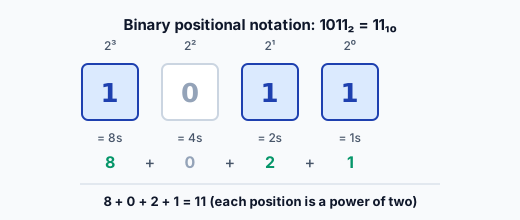
- 1011 = (1×8) + (0×4) + (1×2) + (1×1) = 8 + 0 + 2 + 1 = 11
- 0110 = (0×8) + (1×4) + (1×2) + (0×1) = 0 + 4 + 2 + 0 = 6
- 1111 = 8 + 4 + 2 + 1 = 15 (the max for 4 bits)
- 0000 = 0 (the min)
So 4 bits represent 0 to 15 — that's 2⁴ = 16 different values.
Converting decimal to binary
To go the other way (decimal → binary), find which powers of 2 add up to your number:
- 6 = 4 + 2 → set the 4s and 2s bits → 0110
- 13 = 8 + 4 + 1 → set the 8s, 4s, 1s bits → 1101
- 10 = 8 + 2 → 1010
A systematic method: repeatedly subtract the largest power of 2 that fits. For 13: 13−8=5 (8s bit set), 5−4=1 (4s bit set), 1−1=0 (1s bit set) → 1101.
Bits, nibbles, bytes
The units of binary data:
- Bit: a single binary digit (1 or 0). One HIGH/LOW signal.
- Nibble: 4 bits. Represents 0–15 (one hexadecimal digit).
- Byte: 8 bits. Represents 0–255 (2⁸ = 256 values). The fundamental unit of computer data.
- Word: the natural data size of a processor (often 16, 32, or 64 bits, depending on the chip).
A byte (8 bits) is the workhorse unit. A character, a small number, a colour channel, a sensor reading — all often fit in a byte. When a datasheet says a register is "8-bit," it holds one byte, values 0–255.
Why binary matters for you
Binary shows up constantly in embedded work:
-
Register values. Microcontroller peripherals are configured by setting bits in registers. "Set bit 3 of the config register" is a binary operation. Understanding which bit is which (and binary positions) is essential for low-level work.
-
Pin states. A port of 8 pins can be read/written as a byte — each bit is one pin's HIGH/LOW. Reading "0b10110100" tells you which pins are HIGH.
-
Sensor data. A sensor returns binary numbers. A 10-bit ADC reading is a binary value 0–1023; a 16-bit sensor returns a 2-byte value. Interpreting them requires binary literacy.
-
Communication protocols. I²C, SPI, UART (L5) all move bytes — binary data — between devices. Debugging them means reading binary/hex.
Hexadecimal (a quick preview)
Because long binary numbers are hard to read (11010110), they're often written in hexadecimal (base 16), where each hex digit represents 4 bits (a nibble):
- Binary 1011 = hex B = decimal 11.
- Binary 11010110 = hex D6 = decimal 214.
Hex is just a compact way to write binary — each hex digit is one nibble. You'll see it constantly in code (0xD6), register values, and addresses. Full hex fluency comes with practice; for now, know that hex is shorthand for binary, 4 bits per hex digit.
The big picture
Binary is the substrate of all digital computation. Every number the microcontroller stores, every register it configures, every byte it sends — all binary. The 1s and 0s are just HIGH and LOW voltages (slide 1), produced by transistor switches (L2), combined into the logic and numbers that make a computer.
You don't need to do binary arithmetic in your head constantly — but understanding that data is binary, being able to convert small values, and reading bit positions in a register are core embedded skills.
The next lesson moves from numbers to operations: logic gates, the building blocks that perform the actual computation on these binary values.
The binary number 1011 equals what in decimal?