Transistors: the electronic switch
A transistor is an electronically-controlled switch (and amplifier). A small electrical signal controls a much larger current — letting a tiny microcontroller pin switch a motor, a light, a heater. The transistor is the component that lets low-power logic control high-power loads.
The core idea
A transistor has three terminals. A signal on one terminal controls the current flowing between the other two:
- BJT (bipolar): a small base current controls a larger collector-emitter current.
- MOSFET (field-effect): a gate voltage controls a larger drain-source current.
Either way, the principle is the same: a small control input governs a large output current. That's what makes a transistor a switch (control = on/off) or an amplifier (control = proportional).
Switch vs amplifier
A transistor operates in two broad modes:
-
As a switch (digital): driven fully ON (saturated — conducting hard) or fully OFF (cut off — blocking). Like a relay, but electronic, fast, and silent. This is how transistors control loads: a microcontroller pin switches the transistor ON to power a motor, OFF to stop it.
-
As an amplifier (analog): driven somewhere in between, so the output current is proportional to the input. A small audio signal controls a larger one. This is the analog use — important, but L2 focuses on switching.
For most maker + embedded work, you use transistors as switches. The amplifier mode comes up in analog design later in the ladder.
Why we need transistors
The fundamental problem they solve: a microcontroller pin can't drive much.
A typical GPIO pin can source or sink only about 20mA at the logic voltage (3.3V or 5V). That's enough for an LED, but nowhere near enough for:
- A motor (hundreds of mA to amps).
- A relay coil (tens to hundreds of mA).
- A string of LEDs.
- A heater, a pump, a solenoid.
Connect any of these directly to a GPIO and you exceed the pin's limit — damaging the microcontroller. The transistor is the intermediary: the weak GPIO signal controls the transistor, and the transistor switches the strong load current (drawn from a separate supply that can deliver it).
The two transistor families
You'll work with two families:
BJT (Bipolar Junction Transistor):
- Terminals: collector, base, emitter.
- Current-controlled (base current controls the switch).
- Types: NPN (the common one for low-side switching) and PNP.
- Examples: 2N2222, BC547 (NPN); 2N2907, BC557 (PNP).
MOSFET (Metal-Oxide-Semiconductor Field-Effect Transistor):
- Terminals: drain, gate, source.
- Voltage-controlled (gate voltage controls the switch).
- Types: N-channel (common, like NPN) and P-channel.
- Examples: 2N7000 (small), IRLZ44N / AO3400 (power, logic-level).
- More efficient for switching meaningful currents; the modern default.
What's coming
The next slides cover:
- The NPN transistor switch (low-side) — the simplest and most common switching circuit, and why it needs a base resistor.
- MOSFETs — the modern, efficient switch, and what "logic-level" means.
Then Lesson 3 covers choosing between transistor types (and relays), the full microcontroller-drives-a-load pattern, and reading the datasheet specs that matter.
The transistor is where electronics stops being passive observation and starts being active control. Master the transistor switch and you can make a microcontroller control almost anything.
The NPN transistor switch (low-side)
The NPN low-side switch is the simplest, most common transistor switching circuit. A microcontroller pin controls an NPN transistor that switches a load's ground connection on and off. Understanding this one circuit covers most of what you'll do with transistors.
The circuit
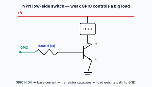
A low-side NPN switch wires up like this:
- Load (e.g., a relay coil, a motor, an LED string) connects from +V supply to the transistor's collector.
- Emitter connects to ground.
- Base connects through a base resistor to the controlling signal (a microcontroller GPIO pin).
"Low-side" means the transistor sits between the load and ground (switching the low/ground side). When the transistor turns on, it completes the load's path to ground, and current flows.
How it switches
- GPIO HIGH → current flows into the base (through the base resistor) → the transistor saturates → collector-emitter conducts → the load gets its ground connection → load ON.
- GPIO LOW → no base current → transistor off → no collector-emitter conduction → load's ground path is broken → load OFF.
So the microcontroller pin (weak, ~20mA max) controls the base, and the transistor switches the load current (which can be much larger, drawn from the +V supply). The pin never carries the load current — it only supplies the small base current.
Why the base resistor is essential
The base resistor is not optional. Here's why:
The base-emitter junction of a BJT behaves like a forward-biased diode — it drops ~0.7V and, without a resistor, would conduct as much current as the source can supply. Connect a GPIO pin directly to the base and:
- The base-emitter "diode" clamps at ~0.7V.
- The pin tries to supply unlimited current into this near-short.
- This exceeds the pin's current limit → damages the microcontroller (and possibly the transistor).
The base resistor limits the base current to a safe value. You want enough base current to fully saturate the transistor (turn it fully on) but not so much that it overloads the pin.
Choosing the base resistor
A rough approach:
- The transistor needs enough base current to switch the load. For a saturated switch, base current ≈ load current ÷ the transistor's gain (hFE), with margin (drive it harder than minimum to ensure full saturation).
- The base resistor sets this current: I_base = (V_GPIO − 0.7V) / R_base.
For example, with a 3.3V GPIO and wanting ~1mA of base current: R_base = (3.3 − 0.7) / 0.001 = 2,600Ω → use a standard 2.2k or 1k. Common base resistor values are 1k–10k for typical small-load switching.
The exact value isn't critical for switching — you just need enough base current to fully saturate the transistor without overloading the pin. 1k is a safe common default for small loads from a logic pin.
Adding the flyback diode (for inductive loads)
If the load is inductive (relay, motor, solenoid), you MUST add the flyback diode across the load (from Lesson 1.3):
- Cathode (stripe) to +V, anode to the collector side.
- This clamps the switch-off spike that would otherwise destroy the transistor.
For a non-inductive load (resistive heater, LED string), no flyback diode is needed — but the moment there's a coil involved, it's mandatory.
The complete low-side NPN switch
Putting it together, the standard circuit:
- Load from +V to collector.
- Emitter to ground.
- Base resistor (1k–10k) from GPIO to base.
- Flyback diode across the load (if inductive).
This is the circuit the P-Check asks you to build (with an LED as the load): GPIO → base resistor → NPN transistor → switching an LED (with its own current-limit resistor). It's the foundational "microcontroller controls a load" building block.
High-side switching (briefly)
There's also high-side switching (the transistor between +V and the load, switching the supply side), which is often done with a PNP transistor or a P-channel MOSFET. It's a bit more involved (the control logic is inverted and referenced to the supply). For most beginner cases, low-side NPN switching is simpler and sufficient — switch the ground side, keep the load's + connected to the supply.
The next slide covers MOSFETs — the modern, efficient alternative to the BJT for switching, and what "logic-level" means for driving them from a microcontroller.
Why does an NPN transistor switching a load from a microcontroller pin need a base resistor?
MOSFETs: the modern switch
MOSFETs are the modern default for switching meaningful currents. Where a BJT is controlled by base current, a MOSFET is controlled by gate voltage — drawing almost no steady current to stay on. That makes MOSFETs efficient and easy to drive.
The key difference: voltage control
A MOSFET's gate is, electrically, like a tiny capacitor — it draws current only briefly while charging/discharging (when switching), and essentially zero current to hold a state. Compare:
- BJT: needs continuous base current to stay on. The base current is "wasted" power and loads the controlling pin.
- MOSFET: needs only a gate voltage to stay on. Once the gate is charged, it holds the state with negligible current.
This makes MOSFETs:
- More efficient (no continuous control current wasted).
- Easier on the controlling pin (the gate barely loads it).
- Better for higher currents (good power MOSFETs have very low on-resistance, wasting little as heat).
For switching anything beyond small loads, the MOSFET is usually the better choice.
The MOSFET switch circuit
An N-channel MOSFET low-side switch is similar to the NPN switch:
- Load from +V to the MOSFET's drain.
- Source to ground.
- Gate to the controlling signal, usually through a small gate resistor (limits the inrush current to the gate capacitance and damps ringing — often 100Ω, sometimes omitted for slow switching).
- Often a pull-down resistor (e.g., 10k) from gate to ground, to ensure the MOSFET turns fully OFF when the controlling pin is floating (e.g., during microcontroller startup).
When the gate goes HIGH (above the threshold), the MOSFET conducts drain→source, switching the load on. When the gate goes LOW, it turns off.
"Logic-level" — the critical spec
Here's the catch that trips people up: a MOSFET needs its gate driven above a threshold voltage (Vgs(th)) to turn on — and to turn on fully (low resistance, not just barely conducting) needs the gate driven well above that threshold.
- Standard MOSFETs often need 10V on the gate to fully turn on. A 3.3V or 5V microcontroller pin can't drive them fully — they'd only partially turn on, conducting poorly and overheating.
- Logic-level MOSFETs are designed to turn on fully at 3.3V or 5V gate drive — perfect for direct control from a microcontroller pin.
The rule: when driving a MOSFET directly from a microcontroller, use a logic-level MOSFET (e.g., IRLZ44N, AO3400, 2N7000 for small loads). Check the datasheet: at your gate voltage (3.3V/5V), is the MOSFET fully on (check Rds(on) at that Vgs)? If the datasheet only specifies full turn-on at 10V, it's not logic-level and won't work directly from a logic pin.
MOSFET vs BJT — when to use which
| Situation | Choose |
|---|---|
| Switching meaningful current (motors, high-power LEDs) | MOSFET (logic-level), for efficiency |
| Small loads, simple, cheap | BJT is fine |
| Driving directly from a 3.3V/5V pin | Logic-level MOSFET or BJT with base resistor |
| Need lowest waste heat at high current | MOSFET (low Rds(on)) |
| Linear/amplifier use | BJT (often easier for analog) |
For switching, the MOSFET is increasingly the default. For tiny loads or learning, the BJT switch (with its base resistor) is simple and forgiving. Both are valid; the choice depends on the current and efficiency needs.
The flyback diode applies to both
Whether you switch an inductive load with a BJT or a MOSFET, the flyback diode is still mandatory. The MOSFET is just as vulnerable to the inductive kick as the BJT. (Power MOSFETs have a built-in "body diode," but it's often not fast/robust enough alone — an explicit flyback diode is still good practice for inductive loads.)
The protection extras
For robust MOSFET switching, two extras are common:
- Gate resistor (~100Ω) in series with the gate — limits the gate-charging current spike and reduces ringing.
- Gate pull-down (~10k) from gate to source — ensures the MOSFET is definitely OFF when the controlling pin is high-impedance (floating), which happens during microcontroller boot before the firmware sets the pin. Without it, a floating gate can leave the MOSFET in an undefined state, randomly turning the load on.
These aren't always strictly necessary for slow, simple switching, but they make the circuit reliable.
Summary
MOSFETs:
- Voltage-controlled (gate voltage), drawing negligible steady current.
- Efficient, ideal for switching meaningful loads.
- Must be logic-level to drive directly from a 3.3V/5V microcontroller pin.
- Use a gate resistor + gate pull-down for robustness.
- Still need a flyback diode for inductive loads.
The next lesson covers the full picture: choosing between transistor, MOSFET, and relay; the complete microcontroller-drives-a-load pattern; and reading the datasheet specs that matter.