Why devices need a common language
In L4 you met the microcontroller — the brain that runs your code. But a brain alone does nothing useful. It has to talk to the world: read sensors, drive displays, command motor drivers, and sometimes chat with other microcontrollers. L5 is about how that conversation happens.
The problem: chips don't automatically understand each other
Imagine two people who each speak a different language trying to coordinate. Even if you connect them with a perfect telephone line, nothing useful happens — they have no shared rules for what the sounds mean. Two chips are the same. Wiring them together is necessary but not sufficient; they also need a shared protocol.
What a protocol actually is
A communication protocol is an agreed set of rules that lets two devices interpret the same electrical signals identically. It pins down things like:
- Voltage levels — what counts as a "1" and a "0" (e.g., 3.3V = high, 0V = low).
- Timing — how fast bits come, and when to read each one.
- Bit order and grouping — which bit first, how many bits make a byte.
- Who starts, and how a message begins and ends.
- Acknowledgement — how the receiver confirms it heard (in some protocols).
A protocol is not the wire. The wire just carries voltage wiggles; the protocol is the agreement that makes those wiggles mean something. UART, SPI, and I²C — the three you'll learn here — are three different such agreements, each with its own rules.
Why there are several protocols, not one
If one protocol were best for everything, there'd be only one. Instead, each makes a different trade-off between speed, number of wires, number of devices, distance, and complexity. A tiny temperature sensor and a high-speed display have very different needs. Part of being a competent engineer is knowing which protocol fits a given job — exactly what Lesson 5 will tie together.
Where this sits in the ladder
L4 gave you the microcontroller with its GPIO, ADC, timers, and comms peripherals. That last one — "UART / SPI / I²C" listed on the MCU block — is what L5 unpacks. By the end you'll understand how the ESP32 in a real build actually reaches the sensors and modules around it, and how L6's power systems get monitored and controlled.
The next slide covers the first big design decision underneath all three protocols: sending bits one-at-a-time (serial) versus all-at-once (parallel) — and why serial won.
A communication 'protocol' between two chips is:
Serial vs parallel: why serial won
Before choosing a protocol, there's a more basic question: do you send all the bits of a byte at once over many wires, or one at a time over a few wires? That's parallel vs serial — and the answer shaped every protocol in this module.
Parallel: all bits at once
In parallel communication, you use one wire per bit. To send a byte (8 bits) in one go, you'd use 8 data wires, all switching together. The receiver reads all 8 simultaneously.
- Pro: potentially fast — a whole byte per clock tick.
- Con: lots of wires. 8 bits = 8 wires (plus ground, plus control). For 16 or 32 bits, it balloons. Those wires cost pins, board space, and money — and at high speed they're hard to keep perfectly in step with each other.
Parallel made sense inside old computers and for short, wide buses, but for connecting a microcontroller to the many small chips around it, the wire count is a dealbreaker.
Serial: one bit at a time
In serial communication, you send the bits one after another down a single data line. The same byte goes out as bit-1, bit-2, bit-3 … in sequence.
- Pro: very few wires — often just one or two data lines regardless of how many bits the message has.
- Con: each bit takes its own moment, so a single line is slower per wire — but modern serial runs so fast that this rarely matters for sensors, displays, and modules.
Why serial won for chip-to-chip links
For connecting a microcontroller to sensors, displays, memory, and other chips, pins and wires are the scarce resource, not raw speed. A microcontroller has a limited number of pins; spending 8+ of them on one parallel peripheral is wasteful when a serial link does the job over 2–4 wires.
So virtually all modern chip-to-chip communication is serial. UART, SPI, and I²C are all serial protocols — they differ in how they manage that one-bit-at-a-time stream, not in whether they're serial.
The one remaining question: timing
If bits arrive one at a time on a line, the receiver faces a crucial problem: how does it know when to read each bit? Read too early or too late and you get the wrong value. There are exactly two answers to this timing question, and they split our three protocols into two camps — the subject of the next slide.
Serial communication sends data:
The three workhorses + the clock question
Bits arrive one at a time on a serial line. The receiver's whole challenge is timing: when, exactly, do I sample the line to read each bit? There are two answers — and they cleanly divide our three workhorse protocols.
Answer 1 — Asynchronous: agree on the speed in advance
In an asynchronous protocol there is no clock wire. Instead, both devices agree beforehand on exactly how fast bits will come (the baud rate). Each side runs its own internal timer at that agreed speed. The sender marks the start of each byte, and the receiver, knowing the speed, samples each bit at the right moment.
- Upside: fewer wires (no clock line).
- Downside: both sides MUST be configured to the same speed — get it wrong and everything garbles.
- This is UART (Lesson 2).
Answer 2 — Synchronous: send a clock alongside the data
In a synchronous protocol there's a dedicated clock line. The controller pulses the clock, and that pulse literally tells the receiver "read the data line now." No prior speed agreement is needed — the clock carries the timing with the data.
- Upside: self-timing, no baud-rate guessing, and can run very fast.
- Downside: an extra wire for the clock.
- This is SPI and I²C (Lessons 3 and 4).
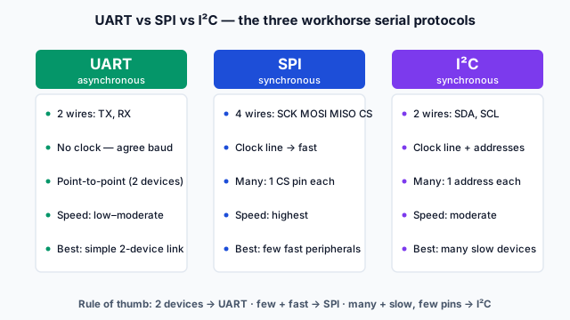
The three workhorses at a glance
| UART | SPI | I²C | |
|---|---|---|---|
| Timing | Asynchronous (no clock) | Synchronous (clock) | Synchronous (clock) |
| Data wires | 2 (TX, RX) | 3 + CS per device | 2 (SDA, SCL) |
| Devices | 2 (point-to-point) | Many (1 CS each) | Many (addresses) |
| Speed | Low–moderate | Highest | Moderate |
| Best for | Simple two-device links | Fast single peripherals | Many slow devices, few pins |
How to read the rest of L5
The next three lessons take one protocol each — UART, then SPI, then I²C — and Lesson 5 puts them side by side as a decision, plus the analog (ADC/DAC) path for sensors that don't speak digital at all. Keep the table above in mind; by the end it should feel obvious which column a given job belongs in.