What an inductor does + where you'll meet them
An inductor stores energy in a magnetic field and resists changes in current — the magnetic counterpart to the capacitor's electric-field charge storage. Inductors are less common in beginner circuits than resistors and capacitors, but they're essential in a few important places.
What an inductor does
An inductor is, at its simplest, a coil of wire. When current flows through it, it creates a magnetic field. Two consequences:
-
It resists changes in current. An inductor "wants" to keep the current flowing at the same level. Try to increase the current suddenly and it pushes back; try to cut the current and it keeps pushing (which causes the inductive "kick" — a voltage spike when you switch off an inductive load).
-
It stores energy magnetically. While current flows, energy is stored in the magnetic field. When the current is interrupted, that energy is released.
This is the mirror image of a capacitor: a capacitor resists voltage changes and stores energy electrically; an inductor resists current changes and stores energy magnetically.
The unit: henries
Inductance is measured in henries (H) — but like the farad, a full henry is large for most electronics. Real inductors are:
- Microhenries (µH): 10⁻⁶ H. Common in DC-DC converters + RF.
- Millihenries (mH): 10⁻³ H. Filters, larger chokes.
Where you'll meet inductors
Inductors show up in a few specific places:
-
DC-DC converters (the big one). Buck (step-down) and boost (step-up) regulators use an inductor as the core energy-transfer element. Every switching regulator — the efficient power converters in solar systems, battery chargers, and most modern power supplies — has an inductor at its heart. The inductor stores energy during one part of the switching cycle and releases it during another, transferring power efficiently.
-
Filtering / EMI suppression. Inductors (often called "chokes" in this role) block high-frequency noise while passing DC. Ferrite beads slipped over a wire are a simple inductor used to suppress interference.
-
RF / tuned circuits. Inductors combined with capacitors form resonant circuits used in radios and wireless. (Deeper RF work is later in the ladder.)
Why inductors are less common for beginners
Compared to resistors and capacitors, you'll place fewer inductors early on:
- Beginner digital circuits (an MCU reading sensors, blinking LEDs) rarely need them.
- They show up mainly when you get into power conversion (switching regulators) and RF.
- Most beginner power needs are met by linear regulators (which use no inductor) rather than switching regulators (which do).
So while resistors and capacitors are in nearly every circuit, inductors are more specialized — important where they appear, but appearing less often in the early projects.
The inductive kick warning
One practical inductor fact worth knowing even early: when you switch OFF current through an inductive load (a relay coil, a motor, a solenoid), the inductor's stored energy produces a sudden high-voltage spike — the "inductive kick" or "flyback." This spike can damage the switching component (a transistor or microcontroller pin).
The fix is a flyback diode (or snubber) across the inductive load, giving the energy a safe path to dissipate. You'll wire these whenever you drive a relay or motor from a transistor — a detail that comes up in L2 (transistors) and L4 (microcontrollers driving loads).
Reading inductor values
Inductors are marked similarly to other components — sometimes a printed value (100µH), sometimes a colour code (similar to resistors but read as inductance), sometimes a numeric code. They're less standardized; when in doubt, the datasheet or a component tester (an LCR meter) confirms the value.
The summary
Inductors:
- Store energy in a magnetic field; resist current changes.
- Measured in henries (µH, mH typical).
- Essential in DC-DC converters, filtering, RF.
- Less common in beginner circuits than R and C.
- Watch for inductive kick when switching inductive loads — use a flyback diode.
The next slide moves from individual components to passive circuits — how resistors and capacitors combine into the building blocks you'll use constantly: voltage dividers and RC filters.
Passive circuits: voltage dividers, RC filters, pull-ups
Resistors and capacitors combine into a few essential building blocks you'll use constantly: the voltage divider, the RC filter, and pull-up/pull-down resistors. Understanding these turns individual components into circuits that do something.
The voltage divider
Two resistors in series across a voltage split it proportionally. Tap the midpoint and you get a fraction of the input.
The formula: Vout = Vin × R2 / (R1 + R2)
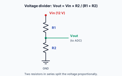
where R1 is the top resistor (toward Vin) and R2 is the bottom (toward ground), and Vout is measured at the midpoint.
Worked examples:
-
Two equal resistors across 5V: Vout = 5 × R/(R+R) = 5 × 1/2 = 2.5V. Equal resistors → half the voltage.
-
Scaling 12V to ~3.3V for an ADC: you want Vout/Vin ≈ 3.3/12 ≈ 0.275. Pick R2/(R1+R2) ≈ 0.275 — for example R1 = 22k, R2 = 8.2k gives 8.2/(22+8.2) = 0.27, so Vout ≈ 12 × 0.27 = 3.26V. Now a 12V signal is safely readable by a 3.3V microcontroller's ADC.
Where you use it:
- Reading a higher voltage with a lower-voltage ADC (battery monitoring, sensor signals).
- Setting a reference voltage for a comparator.
- Potentiometers are adjustable voltage dividers (the wiper taps a variable midpoint).
The precision note: for an ADC divider where the exact ratio matters, use ±1% resistors (per Lesson 1) — ±5% resistors might be off enough to misread the voltage.
The RC filter
A resistor and capacitor together filter signals by frequency. Two basic configurations:
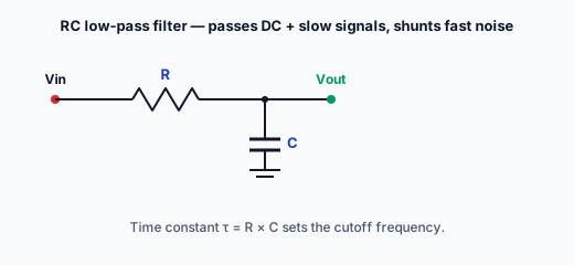
Low-pass filter (R in series, C to ground at the output): passes low frequencies (including DC), blocks high frequencies. Used to smooth noise out of a sensor reading — the slow signal passes; the fast noise is shunted to ground by the capacitor.
High-pass filter (C in series, R to ground): passes high frequencies, blocks DC. Used to remove a DC offset, letting only the changing part of a signal through.
The RC time constant: the speed of an RC circuit is set by τ (tau) = R × C. A larger R or C means slower charging/discharging — a lower filter cutoff frequency, or a longer timing delay. This same RC time constant sets:
- Filter cutoff (which frequencies pass).
- Timing delays (how long a capacitor takes to charge through a resistor).
- Debounce timing (smoothing the noisy contact of a mechanical button).
You don't need the full filter math yet (that's later in the ladder) — but understanding that R and C together set a time/frequency behaviour, tuned by their product, is the foundation.
Pull-up and pull-down resistors
A microcontroller input pin needs a defined voltage. If nothing is driving it, the pin "floats" — it picks up noise and reads unpredictably (sometimes HIGH, sometimes LOW). A pull resistor fixes this:
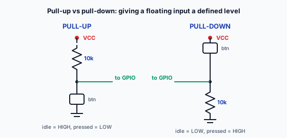
Pull-up: a resistor (typically 4.7k–10k) from the pin to VCC. When nothing else drives the pin, the pull-up holds it HIGH. A button connecting the pin to ground then pulls it LOW when pressed. So: unpressed = HIGH (via pull-up), pressed = LOW.
Pull-down: a resistor from the pin to GND. Holds the pin LOW by default; a button to VCC pulls it HIGH when pressed.
Where you need them:
- Buttons / switches — to give the pin a defined state when the button isn't pressed.
- I²C lines (SDA, SCL) — these require pull-ups to work at all; many breakout boards include them, but some don't.
- Reset / enable pins — to hold them at a default state.
Value choice: 10k is a common default pull-up. Lower values (4.7k) for noisier environments or faster signals (I²C at higher speeds); higher values (100k) to save power. The exact value isn't critical for a simple button — anywhere in the 4.7k–10k range works.
The floating-input trap: the most common beginner microcontroller bug is a floating input — a button wired without a pull resistor, reading randomly. Many microcontrollers have internal pull-ups you can enable in software (saving an external resistor), but you have to remember to turn them on. If a button "sometimes works", a floating input (missing pull) is the first suspect.
Passives as building blocks
This is the payoff of L1: individual passives (resistors, capacitors, inductors) combine into circuits that DO things:
- Voltage divider → scale a voltage.
- RC filter → clean up a signal / set a timing.
- Pull-up/down → give a pin a defined state.
- Decoupling cap → keep a power rail steady.
- Current-limit resistor → protect an LED.
These building blocks appear in nearly every circuit you'll build. Recognizing them — "oh, that's a voltage divider feeding the ADC", "those are the I²C pull-ups" — is what reading a schematic fluently actually means.
The module summary
Across L1:
- Resistors — limit current, drop/divide voltage. Read values from colour bands + SMD codes. Choose value (Ohm's Law), power rating, tolerance.
- Capacitors — store charge; smooth, filter, decouple, time. Ceramic (non-polarised, decoupling), electrolytic (polarised — mind the stripe! — bulk smoothing), film (precision). Read codes; respect polarity.
- Inductors — store energy magnetically; essential in DC-DC converters + RF, less common early. Watch for inductive kick.
- Passive circuits — voltage dividers, RC filters, pull-up/down resistors: the building blocks that combine passives into useful functions.
The P-Check certifies the hands-on skill: identify 5 resistors from their bands AND verify with a multimeter, plus identify a capacitor's value. Reading + measuring passives is the practical foundation that everything above L1 builds on.
With L0 (fundamentals) and L1 (passives) complete, you have the groundwork for L2 (diodes + transistors — the first active components) and the rest of the Technical Ladder. Passives are the supporting cast in every circuit; understanding them is the price of entry to understanding the active components that do the real work.
A voltage divider with two equal resistors across 5V outputs what at the midpoint?
Pull-up and pull-down resistors
Slide body Markdown is missing — author it at library/learn_modules/l1-passive-components/lessons/03/03.md.