What a resistor does + Ohm's Law in practice
A resistor does one thing: it resists the flow of current. That simple property makes it one of the most-used components in every circuit — limiting current, dropping voltage, dividing voltage, and setting reference levels.
The one law that governs resistors
From L0: Ohm's Law, V = I × R. Voltage equals current times resistance. Rearranged, it answers the three questions you'll ask about a resistor constantly:
- What voltage drops across it? V = I × R.
- What current flows through it? I = V / R.
- What resistance do I need? R = V / I.
Every practical resistor decision comes back to one of these three forms. Burn them into memory.
What resistors do in real circuits
Four common jobs:
-
Current limiting. The classic: an LED needs a specific current, but the supply voltage would push too much. A series resistor drops the excess voltage and limits the current to a safe level. (You'll calculate this on the next slides — it's the single most common resistor calculation.)
-
Voltage dividing. Two resistors in series split a voltage proportionally. Used to scale a voltage down — for example, bringing a 12V signal down to something a 3.3V microcontroller ADC can read safely.
-
Pull-up / pull-down. A resistor connecting an input pin to VCC (pull-up) or GND (pull-down) gives the pin a defined default state when nothing else is driving it. Without one, the input "floats" and reads unpredictably. (Covered in Lesson 3.)
-
Setting reference / bias. Resistors set bias points for transistors, reference voltages for comparators, and gain for amplifiers — topics that come in L2 and beyond.
Why current limiting matters so much
The LED example is worth internalizing because it's everywhere. An LED is a diode — it doesn't limit its own current. Connect an LED directly across a supply higher than its forward voltage, and it draws as much current as the supply can deliver — which usually destroys the LED (and sometimes the supply).
The series resistor is the fix. It absorbs the voltage difference and sets the current to a safe value. Nearly every LED you'll ever wire needs one.
Resistors don't care about direction
Unlike diodes, transistors, and electrolytic capacitors, resistors are non-polarised — they work the same in either orientation. You can install a resistor backwards and it behaves identically. This makes them forgiving to work with: there's no wrong way round.
The two things you need to know about any resistor
For any resistor in a circuit, you need:
- Its value (in ohms) — what resistance it provides.
- Its power rating (in watts) — how much power it can dissipate without overheating.
The next slides cover reading the value (from colour bands or SMD codes) and choosing the right value + power rating + tolerance for a job.
Reading resistor values: colour bands + SMD codes
Resistor values are marked two ways: colour bands (on through-hole resistors) and numeric codes (on SMD resistors). Reading both is a core skill — you'll do it constantly on the bench.
Colour bands (through-hole)
Most through-hole resistors have 4 bands. From the end with bands grouped closer:
- Band 1: first significant digit.
- Band 2: second significant digit.
- Band 3: multiplier (number of zeros to add).
- Band 4: tolerance.
The colour code for digits and multiplier:
| Colour | Digit / Multiplier |
|---|---|
| Black | 0 |
| Brown | 1 |
| Red | 2 |
| Orange | 3 |
| Yellow | 4 |
| Green | 5 |
| Blue | 6 |
| Violet | 7 |
| Grey | 8 |
| White | 9 |
Tolerance band: Gold = ±5%, Silver = ±10%, Brown = ±1%.
Worked examples
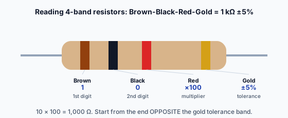
Brown, Black, Red, Gold:
- Brown (1), Black (0) → digits "10"
- Red → multiplier ×100 (two zeros)
- 10 × 100 = 1,000 Ω (1k), ±5%
Red, Red, Brown, Gold:
- Red (2), Red (2) → "22"
- Brown → ×10 (one zero)
- 22 × 10 = 220 Ω, ±5%
Yellow, Violet, Orange, Gold:
- Yellow (4), Violet (7) → "47"
- Orange → ×1,000 (three zeros)
- 47 × 1,000 = 47,000 Ω (47k), ±5%
The trick: first two bands are the number, third band is "how many zeros." Practice on a handful of real resistors and it becomes automatic.
Which end to start from
The tolerance band (gold/silver) is usually slightly separated from the others and is the LAST band. Start reading from the end OPPOSITE the tolerance band. If you read it backwards, you'll get a nonsense value — flip it and re-read.
SMD codes (surface-mount)
SMD resistors are too small for colour bands, so they use a printed numeric code:
3-digit code: first two digits = significant figures, third digit = number of zeros.
472→ 47 + 2 zeros = 4,700 Ω (4.7k)103→ 10 + 3 zeros = 10,000 Ω (10k)220→ 22 + 0 zeros = 22 Ω (note: the 0 means no zeros, so 22Ω, NOT 220Ω)
4-digit code (more precise parts): first three = significant figures, fourth = zeros.
4701→ 470 + 1 zero = 4,700 Ω (4.7k)
'R' notation for values under 10Ω: the R marks the decimal point.
4R7→ 4.7 ΩR47→ 0.47 Ω
Verifying with a multimeter
The reliable way to confirm any resistor's value: measure it with a multimeter in resistance (Ω) mode.
- Set the multimeter to resistance mode (the Ω symbol).
- Touch the probes to the resistor's two leads.
- Read the value.
The measured value should match the colour-band/SMD reading within the tolerance (a 1k ±5% resistor measures between 950Ω and 1,050Ω). If it's wildly off, either you misread the bands or the resistor is damaged.
The P-Check for this module asks you to do exactly this: read 5 resistors from their bands AND verify with a multimeter. Reading + measuring together is the practical resistor-identification skill.
The next slide covers choosing a resistor — not just reading an existing one, but picking the right value, power rating, and tolerance for a job.
A resistor has bands: Brown, Black, Red, Gold. What's its value?
Choosing a resistor: value, power rating, tolerance
Choosing a resistor means picking three things: the value (ohms), the power rating (watts), and the tolerance (precision). Get any one wrong and the circuit misbehaves — or the resistor burns up.
Choosing the value
The value comes from the job, via Ohm's Law. The canonical example — sizing an LED's series resistor:
The problem: an LED needs 20mA at 2V forward voltage. The supply is 5V.
The calculation:
- The resistor must drop the voltage the LED doesn't use: 5V − 2V = 3V across the resistor.
- The same current flows through the resistor and LED (they're in series): 20mA = 0.020A.
- R = V / I = 3 / 0.020 = 150 Ω.
So a 150Ω resistor in series with the LED limits the current to 20mA. This is the most common resistor calculation in hobby + professional electronics — practice it until it's reflexive.
Choosing the power rating
A resistor dissipates power as heat. Exceed its power rating and it overheats, drifts, discolours, or burns. So you check the dissipation against the rating.
Power in the resistor: P = V × I (the voltage across it times the current through it).
For the LED example: P = 3V × 0.020A = 0.06W = 60mW.
Standard through-hole resistors come in power ratings: 1/8W (125mW), 1/4W (250mW), 1/2W (500mW), 1W, and up. For 60mW of dissipation, a standard 1/4W resistor is comfortable (250mW rating, well above the 60mW load).
Rule of thumb: pick a power rating at least 2× the calculated dissipation, for headroom. 60mW dissipation → at least 120mW rating → the standard 1/4W (250mW) is fine.
When power matters more: in power circuits (motor drivers, high-current LEDs, current-sense resistors), dissipation can be watts, and you need genuinely beefy resistors. Always calculate P = V×I (or P = I²R, or P = V²/R) and check the rating.
Choosing the tolerance
Tolerance is how far the actual resistance may deviate from the nominal:
- ±5% (gold) — the everyday default. Fine for current limiting, pull-ups, most jobs.
- ±1% (brown) — precision. Use for voltage dividers feeding an ADC, reference circuits, anywhere the exact ratio matters.
- ±10% (silver) — loose. Rarely worth it now that ±5% is cheap.
When tolerance matters: if you're building a voltage divider to scale 12V down to exactly 3.3V for an ADC, ±5% resistors might be off by enough to misread. ±1% gives you a more accurate ratio. For an LED current limit, ±5% is plenty — the LED doesn't care if it gets 19mA or 21mA.
The standard value problem
Resistors come in standard values (the "E12" series: 10, 12, 15, 18, 22, 27, 33, 39, 47, 56, 68, 82, and decade multiples). Your calculation might give 150Ω (which exists) or 187Ω (which doesn't).
When your calculated value isn't a standard value:
- Round to the nearest standard value — usually fine, since tolerance already allows some slop.
- Round UP for current-limit resistors — a slightly higher resistance means slightly less current, which is the safe direction for an LED.
For the LED example, 150Ω is a standard value, so no rounding needed. If you'd calculated 145Ω, you'd use 150Ω (round up, slightly safer current).
Putting it together
To choose a resistor for a job:
- Value: calculate from Ohm's Law (R = V/I for current limiting, the divider ratio for dividers).
- Round to the nearest standard value (up, for current limits).
- Power rating: calculate dissipation (P = V×I), pick a rating ≥2× that.
- Tolerance: ±5% default; ±1% where the exact value matters.
That's the full resistor-selection process. The next lesson moves to capacitors — a component that does the opposite of a resistor in an important sense: it stores energy rather than dissipating it.
An LED needs 20mA at 2V; supply is 5V. What series resistor value drops the extra voltage?