Why we read schematics
A schematic is a wiring map. It shows every component, every connection, and the order they're connected. If you can read one, you can debug a circuit you've never seen before.
What a schematic gets you
Three things you can't get any other way:
- What's connected to what. "Pin 4 of the regulator goes to ground" is one line on the schematic and ten minutes of tracing on a real board.
- Why a component is there. A decoupling cap on a power pin makes sense the moment you see it sitting between VCC and GND on the schematic. On the physical board, it just looks like another part.
- Where to probe. When something doesn't work, you look at the schematic, decide what voltage should be where, and probe that node with a multimeter. No schematic, no debugging — just guessing.
The shape of a schematic
Schematics aren't drawings of the physical board. They're abstract — components are placed for clarity, not for layout. Signal flow usually moves left-to-right; power rails at the top; ground at the bottom. Nets that visually cross sometimes don't actually connect — only dots (junctions) mean a real connection.
You don't need to draw a schematic in this lesson. You need to read one. The next two slides cover the symbols you'll meet every day: passives (resistor, capacitor, inductor) and actives (diode, transistor, IC).
Where you'll use this
Every BOM starts with a schematic. Every datasheet has one. Every reference design is built around one. Schematic literacy is the price of entry to L1 and everything above.
Passive symbols: resistor, capacitor, inductor
Passives — resistors, capacitors, inductors — are the components that don't switch or amplify; they shape voltage and current passively. You'll see them in every circuit.
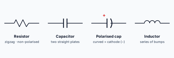
Resistor
- Symbol: zigzag line, or in the IEC standard a plain rectangle. Schematics use whichever the upstream symbol library does — both are correct.
- Value next to it: e.g. "R1 10k" means resistor reference R1, 10 kΩ.
- Reads the same in both directions — resistors are non-polarised.
Common uses: current limiting (LED series resistor), voltage dividing, pull-up / pull-down on a logic input.
Capacitor
Two shapes:
- Non-polarised: two parallel straight lines. Ceramic and film caps. Use it either way around.
- Polarised: two lines, one of them curved (the curve is the negative side, the cathode). Electrolytic caps. Wrong polarity will destroy the part — usually noisily.
You'll often see polarised caps marked with a "+" next to the anode in addition to the curved cathode. On the part itself, electrolytics have a stripe down the cathode side.
Common uses: decoupling (small ceramic across power pins), filtering (larger electrolytic on the supply), timing (RC delays).
Inductor
Symbol: a series of bumps or curved loops. Sometimes annotated with a core type (a line above the curves = air core; bars above = iron/ferrite core).
Common uses: DC-DC converters (the L in a buck or boost regulator), RF tuning, EMI suppression. Less common in beginner circuits than R and C, but every switching-regulator board uses them.
How to tell them apart at a glance
- Zigzag / rectangle → resistor
- Two parallel lines → capacitor (curved one = polarised)
- Series of bumps → inductor
That's the entire vocabulary for passives. You'll see hundreds of these per schematic; the symbols don't change.
A schematic shows a symbol with two parallel plates and a curved line on one side. What is it?
Active symbols: diodes, transistors, ICs
Actives — diodes, transistors, ICs — are the components that switch, amplify, or compute. They're polarised by definition; connecting them wrong is one of the most common ways beginner circuits fail.
Diode
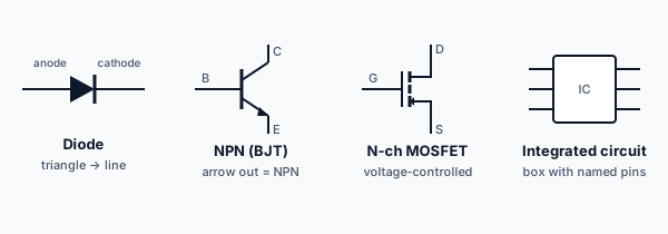
Symbol: a triangle pointing at a vertical line.
- Triangle = anode (current flows in).
- Line = cathode (current flows out).
- Current flows triangle-to-line only. A diode is a one-way valve.
On the physical part, the cathode is usually marked with a stripe. Get this backwards and your circuit either does nothing or destroys the diode (depending on how much current the rest of the circuit is happy to push).
LEDs use the same symbol with arrows pointing away from the diode body (to show it emits light).
Transistor
Two main families you'll meet at L0:
- BJT (bipolar): triangle with three terminals — collector, base, emitter. Arrow on the emitter tells you NPN (arrow pointing out) or PNP (arrow pointing in).
- MOSFET (field-effect): more elaborate symbol — gate (G), drain (D), source (S). N-channel and P-channel variants.
You don't need to design with these yet — that's L2. For now: recognise that a transistor symbol has three terminals (vs the diode's two), and that direction of the arrow matters (it tells you the type and which way current flows in normal operation).
Integrated circuit (IC)
Symbol: a rectangle with pin labels around it. Pin numbers usually run counter-clockwise from the top-left of the chip when viewed from above. The schematic symbol can be drawn pin-for-pin (a literal box with pins) or grouped by function (a "functional" symbol where related pins are pulled together for readability).
Every IC has a datasheet that tells you:
- What each pin is for
- The recommended voltage on each pin
- The absolute maximum voltage on each pin
The next lesson is on reading those datasheets.
Quick recognition
- Two leads, polarised, one-way → diode (or LED)
- Three leads, with an arrow → transistor
- A box with named pins → IC
That's enough to navigate a beginner schematic. The detail of how each one works is L1 and L2.
Which of these symbols indicates current can only flow one way?